
 354
354
We have seen an up-tick in "bad gas valves" in the last year or two. In most cases the valve indeed is not bad or "defective". One of my absolute favorite tools is the Jumper Wire (with alligator clips), this allows me to quickly bypass a switch or thermostat, so I can be as hands free as possible. That being said, a preferred method to testing a gas valve is to apply 24vac directly to the valve either from the transformer, or, from R and C on the control board using my jumper wires. If the valve opens, we can safely assume that it is functional during normal sequence.
So what gives? Why does my valve not open when its connected properly? Why do I see 24vac at the wires to the valve? OR why do I not have 24vac from the board to the valve when its supposed to be there?
IF in the event we do see 24vac but the valve doesn't open, there is a possibility that there is a component in line to the valve that my have a high resistance value. Same goes for if we DO NOT see 24vac. This is where we talk about that sneaky little collector box pressure switch and wiring diagrams. :)
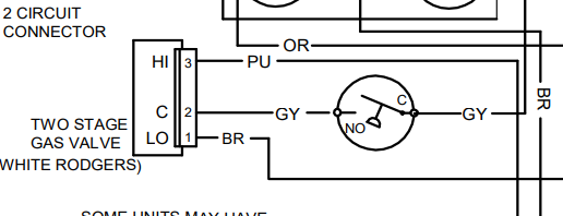
In the diagram here, we can see that there there is a switch tied "in series" or "in line" with the gas valve. This switch, weather its a pressure switch or limit switch, will interrupt the signal to the valve if needed, and usually cause a "Flame Failure" fault or " Ignition lockout" fault. Because of how its wired in series, the control board doesn't even know that this switch exists. So, during testing, IF we see 24v we assume the valve is bad. BUT, what could actually be happening is this switch COULD have high resistance which will not allow the valve to open. IF, we DO NOT see 24v, we assume our board is bad, and after replacing the board, we are back to square one with the valve still not opening.
We should spend a little extra time looking at, understanding, and following wire diagrams on the equipment we service, so we can accurately diagnose what the actual issue is, and avoid that SUPER awkward conversation with homeowners on why there furnace STILL isn't working right.
Oh yeah, and supply yourself with some jumper wires to make life in service much easier!
Key Takeaways:
-
Gas valve issues are often misdiagnosed — the valve may not be bad at all.
-
A jumper wire (with alligator clips) is a valuable tool for bypassing switches or thermostats for hands-free testing.
-
Preferred gas valve test method:
-
Apply 24VAC directly to the valve from the transformer or control board (R and C terminals) using jumper wires.
-
If the valve opens, it’s likely functional.
-
Common Pitfalls to Watch For:
-
24VAC present, but valve doesn't open:
-
A component in line (like a pressure switch) may have high resistance, preventing the valve from opening.
-
-
No 24VAC at the valve:
-
Don’t assume the control board is bad — a faulty in-line switch may be interrupting the signal.
-
Pro Tip:
-
Always study the wiring diagram to understand the sequence of components.
-
Spending extra time diagnosing properly can prevent awkward follow-ups with homeowners.
-
Keep jumper wires on hand — they’ll make your troubleshooting life easier!
Carlos

