
 123
123
Subject: Heat Recovery Refrigerant Branch Unit (RBU) Installation
Introduction:
The purpose of this bulletin is to provide supplementary information for RBU installation, to facilitate effective
brazing. This bulletin is applicable to all production Single and Multi RBU models, UTP-RU**A-F. For compete
instructions for RBU installation, please refer sure applicable Installation Manual and Design and Technical Manual,
D&T.
Discussion:
All Airstage VU-V and VR-II series Heat Recovery systems feature use of a Refrigerant Branch Unit, RBU, to direct
refrigerant high and low pressure flow between heat and cool modes of the connected indoor unit(s). Due to the
solenoid valve arrangement of the RBU, additional steps are required in the field to facilitate nitrogen purging
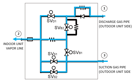
through the low pressure connection of the RBU, labeled as “SUCTION GAS PIPE” on the RBU label. See Fig. 1.
When providing a low pressure nitrogen purge when brazing, a path for nitrogen flow is provided internal to the RBU
between the discharge gas pipe vapor line connection to the indoor unit vapor line . When attempting a
nitrogen purge for brazing the RBU suction gas pipe connection the NC, normally closed solenoid valves SVb1,
SVs1 and SVs2 will inhibit nitrogen flow through the RBU as shown. Thus, an increase in pressure may be interpreted
as a blockage or other restriction in the RBU or piping by the Installer.
In order to provide nitrogen flow between the suction gas pipe and indoor unit vapor line , there are two
primary options for the Installer to consider, depending upon availability of power for the outdoor unit(s) and RBU.
1. Outdoor unit function setting F3:21- requires line voltage power to the outdoor unit and RBU(s).
2. Isolation valve- Installation of a 3rd party refrigerant isolation valve at the suction gas pipe connection.
Fig. 1.– RBU solenoid valve SV arrangement

1. Outdoor Unit Function Setting:
See Fig. 2. This option requires the outdoor unit(s) and RBU(s) to have power applied. In order to provide a path for
nitrogen flow through the suction gas pipe of the RBU, the normally closed solenoid valves must be powered and
remain energized to power the valves open.
Fig. 2.—SV’s powered OPEN (Power must remain ON)
• Outdoor unit Function Setting F3:21– This function setting is initiated at the Primary outdoor unit. F3:21 is
commonly used to drive the indoor unit EEVs OPEN for purging and evacuation, however with Heat Recovery
systems, will power the two-position solenoid valves OPEN.
Table 1.– Outdoor Unit Monitor Mode (Service Manual excerpt)
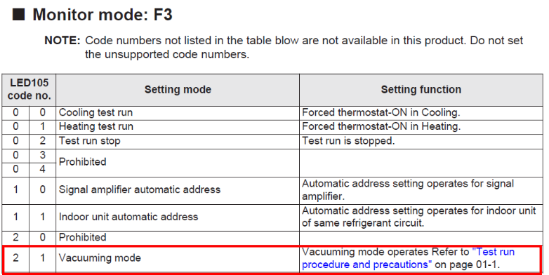
Enter “Vacuuming Mode”- With the outdoor unit(s) and RBU(s) powered and system not operating, use the Primary
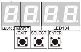
outdoor unit MODE/EXIT, SELECT and ENTER buttons to select:
• Monitor Mode– Select “F3”
• Code number– Select “21”
• Push / hold ENTER until “run” is listed on the 7-segment display:
The video link HERE provides a step-by-step procedure for entering the vacuum mode.
Once the RBU SVs are powered open, the nitrogen purge can commence to facilitate the suction gas pipe braze
connection. Upon completion of suction line brazing, the outdoor unit and RBU may then be powered OFF.
2. Refrigerant isolation valve
See Fig. 3.

Fig. 3.– Isolation valve installed at RBU suction line connection.
This option does not require power to be applied to the outdoor unit or RBU. This option does require the
contractor to furnish and install a 3rd party refrigerant isolation valve between the RBU and the suction line from the
outdoor unit. Although this does not provide a nitrogen purge through the RBU directly, it will provide a purge path
thought the isolation valve to facilitate brazing the suction line connection at the RBU.
IMPORTANT– Ensure the valve orientation is positioned so the gauge port is located between the valve body and
RBU. Prior to brazing, remove the gauge port valve core, open the valve and provide heat protection to the valve
body in accordance wit the valve manufacturers instructions.
With the isolation valve OPEN, the nitrogen purge can commence to facilitate the suction gas pipe braze connection.
IMPORTANT!
WHEN THE 7-SEGMENT DISPLAY SHOWS “poff” (power OFF) DO NOT
REMOVE POWER FROM THE OUTDOOR UNIT AND RBU(S).
THE RBU SOLENOIDS ARE SPRING CLOSED AND MUST REMAIN POWERED
OPEN, TO PROVIDE THE PATH FOR THE NITROGEN PURGE FLOW WHEN
BRAZING.
This bulletin is to provide supplemental instruction for RBU installation. For complete instructions, please refer to
the Installation Manual shipped with each RBU. For digital copies of the Installation Manual, please log onto the
Fujitsu CONNECT site for Airstage V-Series Installation and Design & Technical Manual downloads.
Additional notes
The information in this bulletin is subject to change without notice. Installation procedures for 3rd party isolation
valves shall conform to the manufacturer installation instructions.
To obtain additional support, please contact your regional Distributor TSA, Technical Service Advisor, or Fujitsu
General America Technical Support, [email protected] .

