233
233
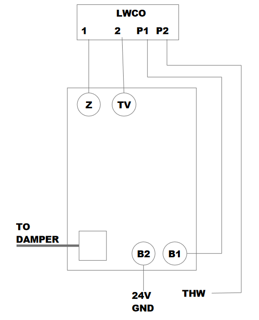
Here is a wiring diagram showing the addition of the low water cutoff in to the control system of a standard boiler. This drawing is specifically the aquastat with the vent damper plug. Z and TV are the opposite sides of the transformer to power LWCO and the we interrupt the heat call and go through the contacts of the LWCO.
Wiring Guide: Integrating a Low Water Cutoff (LWCO) with a Honeywell Aquastat & Vent Damper
In many jurisdictions, a Low Water Cutoff (LWCO) is a code requirement for hot water boilers. When your system also utilizes a motorized vent damper via a Molex plug, the wiring becomes a bit more complex. This guide ensures the safety loop is maintained without bypassing the damper's interlock.
System Compatibility:
Primary Control: Honeywell Aquastat (e.g., L8148E series) with a 4-pin or 6-pin vent damper receptacle.
Secondary Safety: 24VAC Low Water Cutoff (e.g., Hydrolevel Safgard or McDonnell & Miller).
The Logic of the Safety Loop:
For the boiler to fire safely, the circuit must prove two things:
Water Level: Is there enough water in the heat exchanger? (LWCO)
Draft: Is the vent damper fully open? (End Switch)
Step-by-Step Wiring Integration
Phase 1: Identifying Terminals
Before wiring, locate the following on your Honeywell Aquastat:
TV and Z: The 24V thermostat/transformer terminals.
B1: The burner circuit output (usually a 1/4" male spade).
Damper Plug: The factory-installed receptacle for the vent damper.
Phase 2: Wiring the LWCO to Power
To function, the LWCO needs constant 24V power from the Aquastat transformer.
Connect the LWCO Power lead (usually Red) to the Z terminal on the Aquastat.
Connect the LWCO Common lead (usually White) to the TV terminal on the Aquastat.
Phase 3: Breaking the Burner Circuit (The Safety Interlock)
This is where the "cutoff" action happens. You want the LWCO to be able to "break" the signal to the burner if a low-water condition occurs.
Remove the existing wire from the B1 terminal of the Aquastat.
Connect one Yellow wire (Switch leg) from the LWCO to the B1 terminal.
Connect the other Yellow wire from the LWCO to the wire you originally removed from B1.
Note: This places the LWCO in series with the burner, ensuring it kills the flame even if the Aquastat is calling for heat.
Important Note on the Vent Damper Plug
When a vent damper is plugged into a Honeywell Aquastat, an internal fuse is blown during the first cycle. This "permanently" tells the Aquastat that a damper is present.
The Interlock: The burner will not fire unless the damper's end switch proves it is open.
Troubleshooting: If the LWCO is powered and the Aquastat is calling, but B1 has no power, check that the vent damper is fully open.