204
204
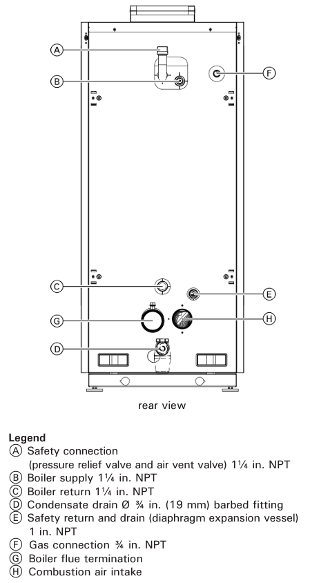
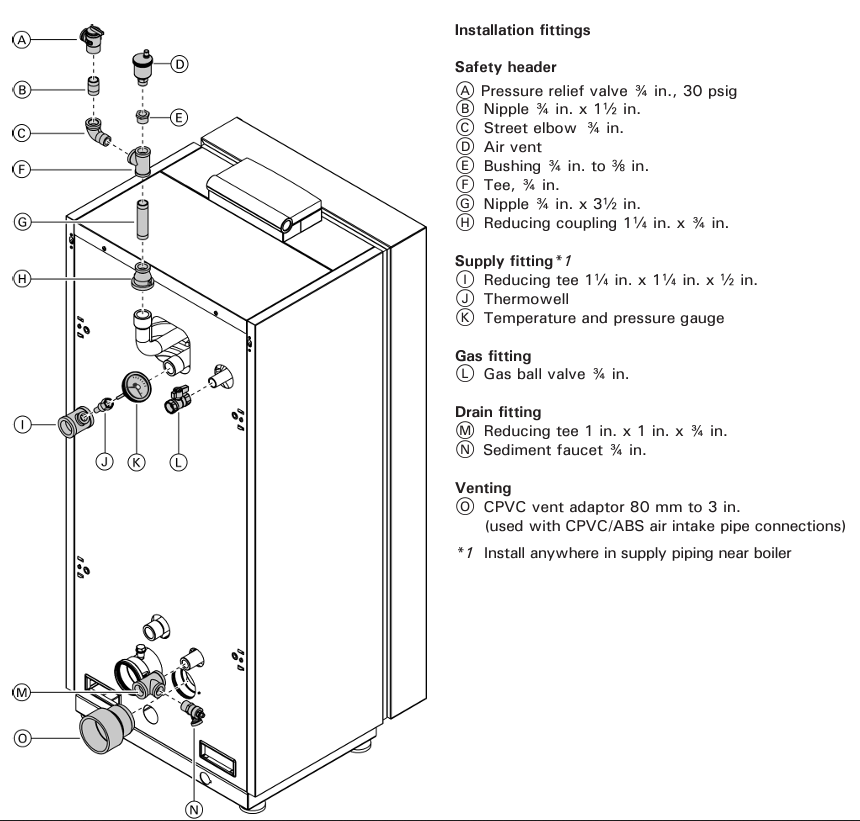
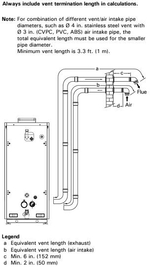
Before applying power to the boiler, we want to review the piping and venting components to ensure they are correct and within specification.
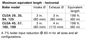
Now that the piping and venting is correct, lets look at the wiring of the sensors, power, and safety devices.
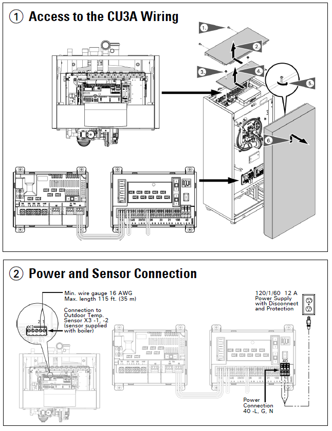
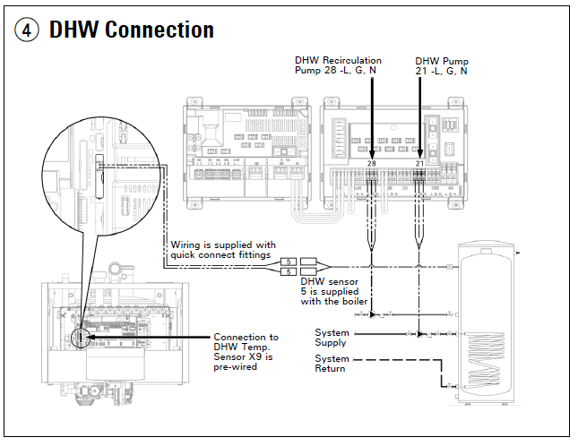
The DHW connection is a small two-wire molex connection that is floating loose in the top of the boiler. You may need to trace back to the connection to the board to see where this may have ended up in during shipping. The pump and external demand connections are to the boards about knee high behind the front cover.

Once all electrical connections are squared away lets go ahead and send power to the boiler. There is a switch under the red control cover that will need to be turned to the "ON" position.
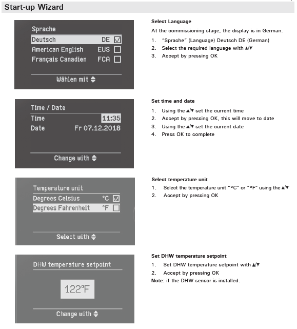
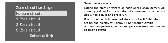
The term "Zone Circuit" on step 5 refers to the number of external demand calls you have coming into the boiler's DE terminals. These are best thought of as "TT" calls, which are usually not needed. For example, if you have a separate zone controller that is actuating zone valves and powering the system pump it is optional to connect the zone board to the boiler. Without a DE call the boiler will simply operate on on warm-weather shut-down and an outdoor reset curve or fixed water setpoint temp continuously based on the HX temp sensors. With a call to DE1 the boiler will operate on an outdoor reset curve or a fixed setpoint when the DE1 dry contact is closed. When using a demand based operation you would select "1 zone circuit". When allowing the boiler to control itself you will select "no zone circuit". See the application guide or service manual for more information on this.