312
312
This long line set application guideline applies to all AHRI listed R-410A air conditioner and heat pump split
system matches of nominal capacity 18,000 to 60,000 Btuh. This guideline will cover installation requirements
and additional accessories needed for split system installations where the line set exceeds 80 feet (24.4 m) in
actual length. The long line sets can have three different configurations (1) Outdoor unit and Indoor unit are at
the same level, (2) Outdoor unit is above the Indoor unit coil, (3) Outdoor unit is below the Indoor unit.
This guideline is meant to provide installation instructions based on most common long line set applications.
Installation variables may affect the system operation.
Contact Technical Services
for variations or applications outside those outlined in this document.
SECTION 1. GENERAL REQUIREMENTS FOR ALL LONG LINE SET APPLICATIONS
1. Equivalent length must be used to determine acceptability of any long line set application. See Section 5
for equivalent length calculations.
2. For any residential split system installed with a long line set, 3/8” liquid line size must be used.
Limiting the liquid line size to 3/8” is critical since an increased refrigerant charge level from having a
larger liquid line could possibly shorten a compressor’s life-span.
a. Exceptions for air conditioning (cooling only) applications, 1/4" liquid line may be used in:
i. 1.5 ton applications for up to 100 equivalent feet (30.5 equivalent meters) with maximum 40’
(12.2 m) vertical lift
ii. 2.0 ton applications for up to 75 equivalent feet (22.9 equivalent meters) with maximum 20’
(6.1 m) vertical lift
b. Exceptions for air conditioning (cooling only) applications, 5/16" liquid line may be used in:
i. 1.5 ton applications for up to 250 equivalent feet (76.2 equivalent meters) with maximum 60’
(18.3 m) vertical lift
ii. 2.0 ton applications for up to 200 equivalent feet (61.0 equivalent meters) with maximum 40’
(12.2 m) vertical lift
iii. 2.5 ton applications for up to 175 equivalent feet (53.3 equivalent meters) with maximum 30’
(9.1 m) vertical lift
3. Most refrigerant tubing kits are supplied with 3/8” (9.5 mm) thick insulation on the suction line. For long
line installations over 80 feet (24.4 m) , if the line set passes through a high ambient temperature zone,
1/2” (12.7 mm) thick suction line insulation is required to reduce loss of capacity. The liquid line must be
insulated if more than 50 feet (15.2 m) of liquid line will pass through an area that might reach temperatures
of 30°F or higher than outdoor ambient. Never attach a liquid line to any uninsulated portion of the
suction line.
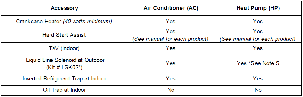
4. A crankcase heater must be installed on any compressor (if crankcase heater is not already factory
installed).
5. Hard start assist kit is required.
6. Use of a thermostatic expansion valve (TXV) is required in all long line set applications. Unit must be
charged to 7 to 9 ºF subcooling at the indoor unit.
7. Maximum equivalent length of line set is:
a. 250 feet (76.2 m) for single stage units with scroll or reciprocating compressors.
b. 150 feet (45.7 m) for single stage units with rotary compressors.
c. 150 feet (45.7 m) for two stage units.
8. Maximum linear length of line set is:
a. 200 feet (61.0 m) for single stage units with scroll or reciprocating compressors.
b. 150 feet (45.7 m) for single stage units with rotary compressors.
c. 150 feet (45.7 m) for two stage units.
9. Low voltage wiring. Verify low voltage wire gauge is adequate for the length used due to increased line
set application.
10. Vibration and Noise: In long line applications, refrigerant tubing is highly prone to transmit noise and
vibration to the adjoining structure. Use adequate vibration-isolating hardware when mounting line set to
structural members.
11. Heat Pump Application Only. Liquid line solenoid must be installed less than 2 feet (61cm) from the
outdoor unit following the solenoid supplier information for installation.
12. Heat Pump Application Only. Heating piston change (in the outdoor unit) is not required.
13. Final Charge Adjustment. All units must have refrigerant charge verified by proper adjustment of
subcooling at the indoor unit after initial charge adjustment per Section 5. Proper adjustment means
pressure and temperature of the liquid line at the indoor unit must be measured to calculate subcooling at
the indoor unit. If subcooling at the indoor unit is less than 7°F, then additional refrigerant must be added
until this subcooling level is achieved. If subcooling at the indoor unit is more than 9°F, then refrigerant
must be removed until this subcooling level is achieved.
SECTION 2. OUTDOOR UNIT AND INDOOR UNIT ARE AT THE SAME ELEVATION

1. In a completely horizontal installation with a long line set where the indoor unit is at the same altitude as
(or slightly below) the outdoor unit, the line set should be sloped continuously towards the indoor unit. This
helps reduce refrigerant migration to the outdoor unit during a system’s off-cycle.
2. The maximum elevation (vertical) difference for this section to be applicable is 10 feet (3.0 m) separation
between outdoor unit and indoor unit. If outdoor unit is more than 10 feet (3.0 m) above indoor unit use
Section 3. If outdoor unit is more than 10 feet (3.0 m) below indoor unit use Section 4.
3. Inverted suction loop is not required at either unit.
4. An accumulator is not required for air conditioners (accumulators are factory installed on heat pumps).
5. An oil trap at the indoor unit is not required.
6. Liquid Line Solenoid not required if non-bleed TXV is used on the outdoor unit.
SECTION 3. OUTDOOR UNIT IS ABOVE THE INDOOR UNIT
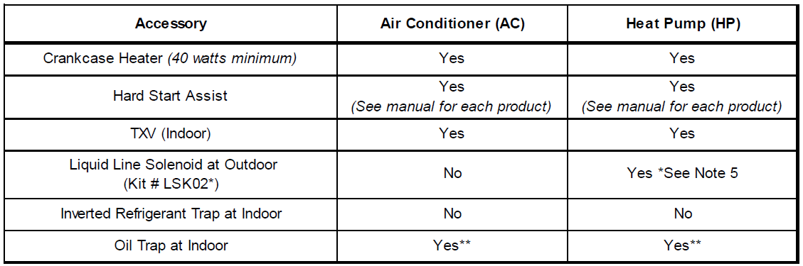
**An oil trap at the indoor unit is required if the elevation difference exceeds 80' (24.4 m).
1. Suction line must be sloped continuously towards the indoor unit.
2. The maximum elevation (vertical) difference between the outdoor unit and indoor unit is:
a. not restricted in this configuration for single stage air conditioning units (must adhere to
maximum equivalent length).
b. 80 feet (24.4m) for single stage heat pump units. Exception: 200ft (61 m) vertical separation allowed
for 14 SEER Long Line Set models and 16 SEER single stage HP models.
c. 25 feet (7.6 m) for two stage units.
3. Inverted suction loop is not required at either unit.
4. An accumulator is not required for air conditioners (accumulators are factory installed on heat pumps).
5. Liquid Line Solenoid not required if non-bleed TXV is used on the outdoor unit.
SECTION 4. OUTDOOR UNIT IS BELOW THE INDOOR UNIT
1. The maximum elevation (vertical) difference between the outdoor unit and the indoor unit is 80 feet
(24.4 m).
2. Suction line must be installed in a manner to prevent liquid migration to the outdoor unit from the
indoor unit (see following note 3).
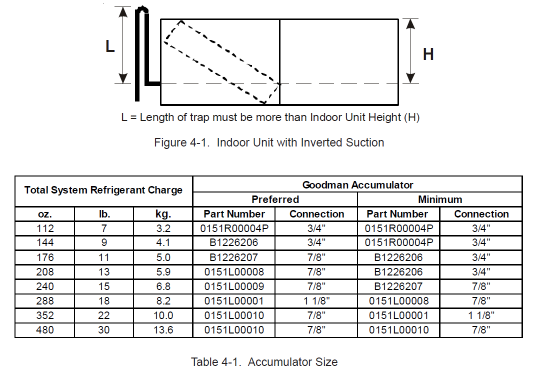
3. An inverted suction line trap must be installed on the suction line just before the inlet to the indoor unit
(see Figure 4-1). The top of the inverted loop must be slightly above the top of the indoor unit coil and
can be created simply by brazing two 90° long radius elbows together if a bending tool is unavailable.
Properly support and secure the inverted loop to the nearest point on the indoor unit or adjacent structure.
4. Line sets over 79 feet require an accumulator to be added (external to the outdoor unit, within 2 linear feet
(61 linear centimeters) of the outdoor unit) for air conditioning installations. See Table 4-1 for accumulator
selection. Adapter fittings at the accumulator connection may be required. Do NOT install an accumulator
in the suction line set in heat pump applications.
5. Liquid Line Solenoid not required if non-bleed TXV is used on the outdoor unit.
SECTION 5. CALCULATIONS - TUBING EQUIVALENT LENGTH, TUBE SIZE AND
REFRIGERANT
1. In long line applications the “equivalent line length” is the sum of the straight length portions of the suction
line plus losses (in equivalent length) from 45 and 90 degree bends. Add the total straight (lineal) length
of tubing to the equivalent length of elbows and bends to get total equivalent length.
Equivalent length = LengthHorizontal + LengthVertical + Losses from bends (see Table 5-1)
2. Table 5-1 lists the equivalent length gained from adding bends to the suction line. Properly size the suction
line to minimize capacity loss.
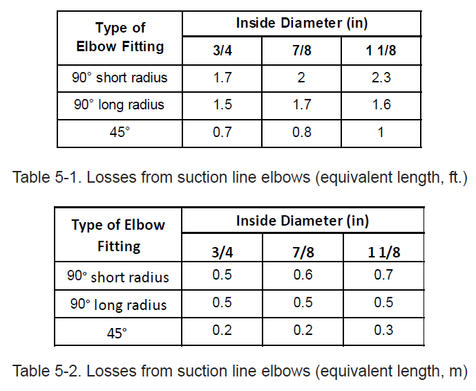
Table 5-1. Losses from suction line elbows (equivalent length, ft.)
EXAMPLE: 3/4” suction line using 3/4” elbows
150 feet of straight tubing + (four short radius elbows x1.7) + (2 long radius elbows x1.5) =
150 + 3.4 + 3 = 156.4 equivalent feet
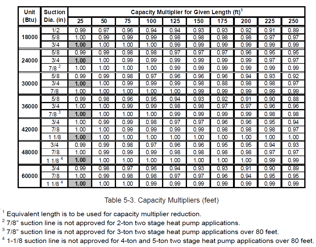
3. Table 5-2 lists multiplier values to recalculate system cooling capacity as a function of a system’s equivalent
line length (as calculated from the suction line) and the selected suction tube size.
NOTE: Select the proper suction tube size based on equivalent length of the suction line
(see Tables 5-1 and 5-2) and recalculated system capacity.
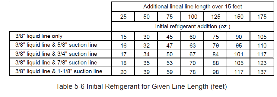
4. Refrigerant Quantity Adjustment. All residential R-410A outdoor units are factory charged for 15 feet
(4.6 m) of line set.
To calculate the initial amount of extra refrigerant (in ounces):
a. Subtract 15 feet (4.6 m) from the total linear (not equivalent) length of actual line set
b. Multiply that value by 0.6 (oz. per foot) or 17.0 (g per meter) of R-410A refrigerant
c. This will be the initial amount of R-410A refrigerant that must be added prior to final
charge adjustment.
All systems must have final charge adjustment performed as required in Section 1. In most residential
applications a minimal amount of additional refrigerant will be needed to account for the volume in the
suction line. For some applications using 1 1/8” suction line and/or over 150 feet of lineal length (45.7 m),
approximately 3 pounds (1.4 kg) of additional refrigerant may be needed to account for the suction line.
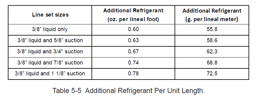
For a more precise calculation of refrigerant needs use Table 5-3. The additional refrigerant for given line
lengths can be found in Table 5-4.