
 160
160
Here is some info on the 19 Series Units form Daikin. Submittals and all are attached... Please see documents for full story....
0.75 - 2.0 Ton Single Split Heat Pump Up to 19 SEER / 9 HSPF / 12.5 EER
MODELS:

| BTUH | Heat Pump |
Wall Mounted |
SEER | EER | HSPF | COP | Line Set | Max Length (Total/Vertical) |
MOCP | Cooling (AHRI 95⁰ F) |
Cooling (Min/Max) |
Heating (AHRI 47⁰ F) |
Heating (Min/Max) |
Heating (AHRI 17⁰ F) |
Max Heat/COP (5⁰ F DB/WB) |
||||||||||||||||||||||||||||||||||||||||||||||||||||||||||||||||||||||||||||||
| 9,000 | RX09AXVJU | FTX09AXVJU | 19.00 | 12.50 | 10.00 | 4.07 | 1/4" x 3/8" | 66' / 49' | 15 | 8,900 | 4,400/10,200 | 10,000 | 4,400/13,000 | 5,700 | 6,839/2.39 | ||||||||||||||||||||||||||||||||||||||||||||||||||||||||||||||||||||||||||||||
| 12,000 | RX12AXVJU | FTX12AXVJU | 19.00 | 12.50 | 10.00 | 3.80 | 1/4" x 3/8" | 66' / 49' | 15 | 10,900 | 4,400/13,300 | 13,500 | 4,400/16,400 | 8,600 | 8,449/2.34 | ||||||||||||||||||||||||||||||||||||||||||||||||||||||||||||||||||||||||||||||
| 18,000 | RX18AXVJU | FTX18AXVJU | 18.50 | 12.50 | 9.00 | 3.60 | 1/4" x 1/2" | 98' / 65' | 20 | 18,000 | 5,500/20,000 | 21,600 | 5,500/24,000 | 12,700 | 9,680 | ||||||||||||||||||||||||||||||||||||||||||||||||||||||||||||||||||||||||||||||
| 24,000 | RX24AXVJU | FTX24AXVJU | 19.00 | 12.20 | 9.00 | 3.45 | 1/4" x 5/8" | 98' / 65' | 20 | 21,200 | 5,500/24,000 | 23,600 | 5,800/27,600 | 15,300 | 10,580 | ||||||||||||||||||||||||||||||||||||||||||||||||||||||||||||||||||||||||||||||
| BTUH | AC Only | Wall Mounted |
SEER | EER | HSPF | COP | Line Set | Max Length (Total/Vertical) |
MOCP | Cooling (AHRI 95⁰ F) |
Cooling (Min/Max) |
Heating (5⁰ F DB/WB) |
|||||||||||||||||||||||||||||||||||||||||||||||||||||||||||||||||||||||||||||||||
| 9,000 | RK09AXVJU | FTK09AXVJU | 19.00 | 12.50 | - | - | 1/4" x 3/8" | 66' / 49' | 15 | 8,900 | 4,400/10,200 | PHASING OUT CY23-Q1 thru CY23-Q3, replaced by 20.2 SEER2 HP & AC Systems. Confirm Availability |
|||||||||||||||||||||||||||||||||||||||||||||||||||||||||||||||||||||||||||||||||
| 12,000 | RK12AXVJU | FTK12AXVJU | 19.00 | 12.50 | - | - | 1/4" x 3/8" | 66' / 49' | 15 | 10,900 | 4,400/13,300 | ||||||||||||||||||||||||||||||||||||||||||||||||||||||||||||||||||||||||||||||||||
| 18,000 | RK18AXVJU | FTK18AXVJU | 18.50 | 12.50 | - | - | 1/4" x 1/2" | 98' / 65' | 20 | 18,000 | 5,500/20,000 | ||||||||||||||||||||||||||||||||||||||||||||||||||||||||||||||||||||||||||||||||||
| 24,000 | RK24AXVJU | FTK24AXVJU | 19.00 | 12.20 | - | - | 1/4" x 5/8" | 98' / 65' | 20 | 21,200 | 5,500/24,000 | ||||||||||||||||||||||||||||||||||||||||||||||||||||||||||||||||||||||||||||||||||
Optional Wired Controls: BRC944B2-A08
Optional Wi-Fi Adaptors: AZAI6WSCDKB
Low Ambient Operation: Low Ambient Cooling to 50 Degrees(standard), -4 with wind baffle installed
Wind Baffle: KPW937F4 (09 & 12) / KPW063B4E (18 & 24)
Drain Pan Heater: KEH067A41EA (09 & 12) / KEH063A4EA (18 & 24)
Line Sets: 10 ft. min. length, additional charge required over 33 feet @ 0.21 oz/ft.
Condensate Lift Pumps: DACA-CP1-1 Aspen Mini Univolt Inline Pump / DACA-CP3-1 Sauermann Si30 Mini Inline Condensate Pump / DACA-CP4-1 Aspen Mini White (External) Univolt Pump Kit (or equal)
Installation (Wiring): Use 4-Wire, 14AWG, Stranded, Non-Shielded Wire to Connect Outdoor to Indoor. Only Break L1 for proper condensate pump wiring (breaking L3 will result in a U4 Error Code).
Installation (General): Mount outdoor units MINIMUM of 2" above anticipated snowfall. Always offer stand, disconnect, whip and pad. Wind Baffles recommended for all low temperature heating applications.
Torque Ratings For Flare Nuts:
| Pipe Size, mm (in) | Torque, Nm/(ft-lb) | ||||||||||||||||||||
| 6.40 (1/4") | 18 (13.3) | ||||||||||||||||||||
| 9.52 (3/8") | 42 (31.0) | ||||||||||||||||||||
| 12.70 (1/2") | 55 (40.6) | ||||||||||||||||||||
| 15.88 (5/8") | 65 (48.0) | ||||||||||||||||||||
| 19.05 (3/4") | 78 (57.6) | ||||||||||||||||||||
Low Ambient Cooling Jumper Settings:

| Fault Diagnosis | ||||||||||||||||||||||||||||||||||||||||||||||||||||||||||||||||||||||||||||||||||
|
||||||||||||||||||||||||||||||||||||||||||||||||||||||||||||||||||||||||||||||||||
   |
||||||||||||||||||||||||||||||||||||||||||||||||||||||||||||||||||||||||||||||||||
|
||||||||||||||||||||||||||||||||||||||||||||||||||||||||||||||||||||||||||||||||||
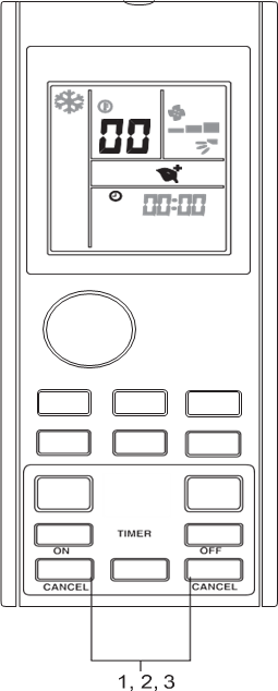
| 2. Press or to check on the error code. • Press on the button repeatedly until a long "beep" acknowledgement heard from the indoor unit. |
||||||||||||||||||||||||||||||||||||||||||||||||||||||||||||||||||||||||||||||||||
| ■ To exit from error code diagnosis 3. Press and hold or button for 5 seconds. • The code display will cancel itself if the button is not pressed for 1 minute. |
||||||||||||||||||||||||||||||||||||||||||||||||||||||||||||||||||||||||||||||||||
| n Note | ||||||||||||||||||||||||||||||||||||||||||||||||||||||||||||||||||||||||||||||||||
|
||||||||||||||||||||||||||||||||||||||||||||||||||||||||||||||||||||||||||||||||||
| ■ Error code definition | ||||||||||||||||||||||||||||||||||||||||||||||||||||||||||||||||||||||||||||||||||
| Error Code | Meaning | |||||||||||||||||||||||||||||||||||||||||||||||||||||||||||||||||||||||||||||||||
| 00 | Normal | |||||||||||||||||||||||||||||||||||||||||||||||||||||||||||||||||||||||||||||||||
| A1 | Indoor PCB error | |||||||||||||||||||||||||||||||||||||||||||||||||||||||||||||||||||||||||||||||||
| A3 | Drain pump abnormal | |||||||||||||||||||||||||||||||||||||||||||||||||||||||||||||||||||||||||||||||||
| A5 | Antifreeze | |||||||||||||||||||||||||||||||||||||||||||||||||||||||||||||||||||||||||||||||||
| A6 | Indoor fan motor abnormal | |||||||||||||||||||||||||||||||||||||||||||||||||||||||||||||||||||||||||||||||||
| AH | Electrical air cleaner abnormal | |||||||||||||||||||||||||||||||||||||||||||||||||||||||||||||||||||||||||||||||||
| C4 | Indoor heat exchanger (1) thermistor short / open | |||||||||||||||||||||||||||||||||||||||||||||||||||||||||||||||||||||||||||||||||
| C5 | Indoor heat exchanger (2) thermistor short / open | |||||||||||||||||||||||||||||||||||||||||||||||||||||||||||||||||||||||||||||||||
| C7 | Louver limit switch error | |||||||||||||||||||||||||||||||||||||||||||||||||||||||||||||||||||||||||||||||||
| C9 | Indoor room thermistor short / open | |||||||||||||||||||||||||||||||||||||||||||||||||||||||||||||||||||||||||||||||||
| E1 | Outdoor PCB error | |||||||||||||||||||||||||||||||||||||||||||||||||||||||||||||||||||||||||||||||||
| E3 | High pressure protection | |||||||||||||||||||||||||||||||||||||||||||||||||||||||||||||||||||||||||||||||||
| E4 | Low pressure protection | |||||||||||||||||||||||||||||||||||||||||||||||||||||||||||||||||||||||||||||||||
| E5 | Compressor motor lock / compressor overload | |||||||||||||||||||||||||||||||||||||||||||||||||||||||||||||||||||||||||||||||||
| E6 | Compressor start-up error | |||||||||||||||||||||||||||||||||||||||||||||||||||||||||||||||||||||||||||||||||
| E7 | Outdoor DC fan motor lock | |||||||||||||||||||||||||||||||||||||||||||||||||||||||||||||||||||||||||||||||||
| E8 | AC input overcurrent | |||||||||||||||||||||||||||||||||||||||||||||||||||||||||||||||||||||||||||||||||
| E9 | EXV error | |||||||||||||||||||||||||||||||||||||||||||||||||||||||||||||||||||||||||||||||||
| EA | 4 way valve error | |||||||||||||||||||||||||||||||||||||||||||||||||||||||||||||||||||||||||||||||||
| F3 | Discharge pipe overheat | |||||||||||||||||||||||||||||||||||||||||||||||||||||||||||||||||||||||||||||||||
| F6 | Heat exchanger overheat | |||||||||||||||||||||||||||||||||||||||||||||||||||||||||||||||||||||||||||||||||
| H0 | Compressor sensor system error | |||||||||||||||||||||||||||||||||||||||||||||||||||||||||||||||||||||||||||||||||
| H3 | High pressure switch error | |||||||||||||||||||||||||||||||||||||||||||||||||||||||||||||||||||||||||||||||||
| H6 | Compressor feedback detection error | |||||||||||||||||||||||||||||||||||||||||||||||||||||||||||||||||||||||||||||||||
| H7 | Fan motor overload / overcurrent / sensor abnormal | |||||||||||||||||||||||||||||||||||||||||||||||||||||||||||||||||||||||||||||||||
| H8 | AC current sensor error | |||||||||||||||||||||||||||||||||||||||||||||||||||||||||||||||||||||||||||||||||
| Error Code | Meaning | |||||||||||||||||||||||||||||||||||||||||||||||||||||||||||||||||||||||||||||||||
| H9 | Outdoor air thermistor short/open | |||||||||||||||||||||||||||||||||||||||||||||||||||||||||||||||||||||||||||||||||
| J1 | Pressure sensor error | |||||||||||||||||||||||||||||||||||||||||||||||||||||||||||||||||||||||||||||||||
| J3 | Compressor discharge pipe thermistor short / open / misplaced | |||||||||||||||||||||||||||||||||||||||||||||||||||||||||||||||||||||||||||||||||
| J5 | Suction pipe thermistor short / open | |||||||||||||||||||||||||||||||||||||||||||||||||||||||||||||||||||||||||||||||||
| J6 | Outdoor heat exchanger thermistor short / open | |||||||||||||||||||||||||||||||||||||||||||||||||||||||||||||||||||||||||||||||||
| J7 | Subcooling heat exchanger thermistor short / open | |||||||||||||||||||||||||||||||||||||||||||||||||||||||||||||||||||||||||||||||||
| J8 | Liquid pipe thermistor short / open | |||||||||||||||||||||||||||||||||||||||||||||||||||||||||||||||||||||||||||||||||
| J9 | Gas pipe thermistor short / open | |||||||||||||||||||||||||||||||||||||||||||||||||||||||||||||||||||||||||||||||||
| L1 | Inverter outdoor PCB error | |||||||||||||||||||||||||||||||||||||||||||||||||||||||||||||||||||||||||||||||||
| L3 | Outdoor control box overheat | |||||||||||||||||||||||||||||||||||||||||||||||||||||||||||||||||||||||||||||||||
| L4 | Heat sink overheat | |||||||||||||||||||||||||||||||||||||||||||||||||||||||||||||||||||||||||||||||||
| L5 | IPM error / IGBT error | |||||||||||||||||||||||||||||||||||||||||||||||||||||||||||||||||||||||||||||||||
| L8 | Inverter compressor overcurrent | |||||||||||||||||||||||||||||||||||||||||||||||||||||||||||||||||||||||||||||||||
| L9 | Compressor overcurrent prevention | |||||||||||||||||||||||||||||||||||||||||||||||||||||||||||||||||||||||||||||||||
| LC | Communication error (outdoor control PCB and inverter PCB) | |||||||||||||||||||||||||||||||||||||||||||||||||||||||||||||||||||||||||||||||||
| P1 | Open phase or voltage unbalance | |||||||||||||||||||||||||||||||||||||||||||||||||||||||||||||||||||||||||||||||||
| P4 | Heat sink thermistor short / open | |||||||||||||||||||||||||||||||||||||||||||||||||||||||||||||||||||||||||||||||||
| PJ | Capacity setting error | |||||||||||||||||||||||||||||||||||||||||||||||||||||||||||||||||||||||||||||||||
| U0 | Insufficient gas | |||||||||||||||||||||||||||||||||||||||||||||||||||||||||||||||||||||||||||||||||
| U2 | DC voltage out of range | |||||||||||||||||||||||||||||||||||||||||||||||||||||||||||||||||||||||||||||||||
| U4 | Communication error | |||||||||||||||||||||||||||||||||||||||||||||||||||||||||||||||||||||||||||||||||
| U7 | Communication error (outdoor control PCB and IPM PCB) | |||||||||||||||||||||||||||||||||||||||||||||||||||||||||||||||||||||||||||||||||
| UA | Installation error | |||||||||||||||||||||||||||||||||||||||||||||||||||||||||||||||||||||||||||||||||
| UF | Piping & wiring installation mismatch / wrong wiring / insufficient gas | |||||||||||||||||||||||||||||||||||||||||||||||||||||||||||||||||||||||||||||||||
| UH | Antifreeze (other rooms) | |||||||||||||||||||||||||||||||||||||||||||||||||||||||||||||||||||||||||||||||||
| n Note | ||||||||||||||||||||||||||||||||||||||||||||||||||||||||||||||||||||||||||||||||||
| After connecting to wireless LAN adapter, remote controller settings prevail over WLAN apps setting. |
||||||||||||||||||||||||||||||||||||||||||||||||||||||||||||||||||||||||||||||||||
| TROUBLESHOOTING | ||||||||||||||||||||||||||||||||||||||||||||||||||||||||||||||||||||||||||||||||||
| For any enquiries on spare parts please contact your authorized dealer. If any malfunction of the air conditioner unit is noted, immediately switch off the power supply to the unit. Check the following fault conditions and causes for some simple troubleshooting tips. | ||||||||||||||||||||||||||||||||||||||||||||||||||||||||||||||||||||||||||||||||||
| Fault | Causes / Action | |||||||||||||||||||||||||||||||||||||||||||||||||||||||||||||||||||||||||||||||||
| 1. The compressor does not operate 3 minutes after the air conditioner unit is started. | – Protection against frequent starting. Wait for 3 to 4 minutes for the compressor to start operating. | |||||||||||||||||||||||||||||||||||||||||||||||||||||||||||||||||||||||||||||||||
| 2. The air conditioner unit does not operate. | – Power failure, or the fuse needs to be replaced. – The power plug is disconnected. – It is possible that your delay timer has been set incorrectly. – If the fault persists after all these verifications, please contact the air conditioner unit installer. |
|||||||||||||||||||||||||||||||||||||||||||||||||||||||||||||||||||||||||||||||||
| 3. The air flow is too low. | – The air filter is dirty. – The doors or windows are open. – The air suction and discharge are clogged. – The regulated temperature is not high enough. |
|||||||||||||||||||||||||||||||||||||||||||||||||||||||||||||||||||||||||||||||||
| 4. Discharge air flow has bad odor. | – Odors may be caused by cigarettes, smoke particles, perfume etc. which might have adhered onto the coil. | |||||||||||||||||||||||||||||||||||||||||||||||||||||||||||||||||||||||||||||||||
| 5. Condensation on the front air grille of the indoor unit. | – This is caused by air humidity after an extended long period of operation. – The set temperature is too low, increase the temperature setting and operate the unit at high fan speed. |
|||||||||||||||||||||||||||||||||||||||||||||||||||||||||||||||||||||||||||||||||
| 6. Water flowing out from the air conditioner unit. | – Switch off unit and call dealer. | |||||||||||||||||||||||||||||||||||||||||||||||||||||||||||||||||||||||||||||||||
| 7. Insufficient heating during heating operation (Multi Split Inverter System) | – If more than one room are being heated simultaneously during winter, it is possible that more time is needed to warm up the rooms. – Switch on heating operation in one room and continue to operate up to a certain extent before heating up the other room. |
|||||||||||||||||||||||||||||||||||||||||||||||||||||||||||||||||||||||||||||||||
| 8. Insufficient cooling during cooling operation (Multi Split Inverter System) | – If more than one room are being cooled simultaneously, it is possible that more time is needed to cool down the rooms. – Switch on cooling operation in one room and continue to operate up to a certain extent before cooling down the other room. |
|||||||||||||||||||||||||||||||||||||||||||||||||||||||||||||||||||||||||||||||||
| If the fault persists, please call your local dealer / serviceman. | ||||||||||||||||||||||||||||||||||||||||||||||||||||||||||||||||||||||||||||||||||
| Accessories List Accessories List |
||||||||||||||||||||||||||||||||||||||||||||||||||||
| Optional Accessories | Model Number | |||||||||||||||||||||||||||||||||||||||||||||||||||
| Indoor Unit | Wired Controller | BRC51D61 | ||||||||||||||||||||||||||||||||||||||||||||||||||
| Wireless Interface Adapter | BRP072A43 | |||||||||||||||||||||||||||||||||||||||||||||||||||
| Outdoor Unit | Air Directional Change Grille (Class 09/12) | KPW937F4 | ||||||||||||||||||||||||||||||||||||||||||||||||||
| Air Directional Change Grille (Class 18/24) | KPW063B4E | |||||||||||||||||||||||||||||||||||||||||||||||||||
| Drain Pan Heater (Class 09/12) | FTDBHMS, KEH067A41E | |||||||||||||||||||||||||||||||||||||||||||||||||||
| Drain Pan Heater (Class 18/24) | KEH063A4EA | |||||||||||||||||||||||||||||||||||||||||||||||||||
| Outdoor Unit Protection Net Grille (Class 09/12) | KKG067A41 | |||||||||||||||||||||||||||||||||||||||||||||||||||
| Outdoor Unit Protection Net Grille (Class 18/24) | - |
|
||||||||||||||||||||||||||||||||||||||||||||||||||

