Viessmann 200 Series CI2 Application Guide

Sep 20, 2023
 198
198
CI2 Application Guide Highlights
When hooking up ECM pumps to these boilers, it is suggested that you use an isolation relay on the boiler contacts to enable pump. This way the pumps computer is powered on at all time.
See full guide for piping suggestions.

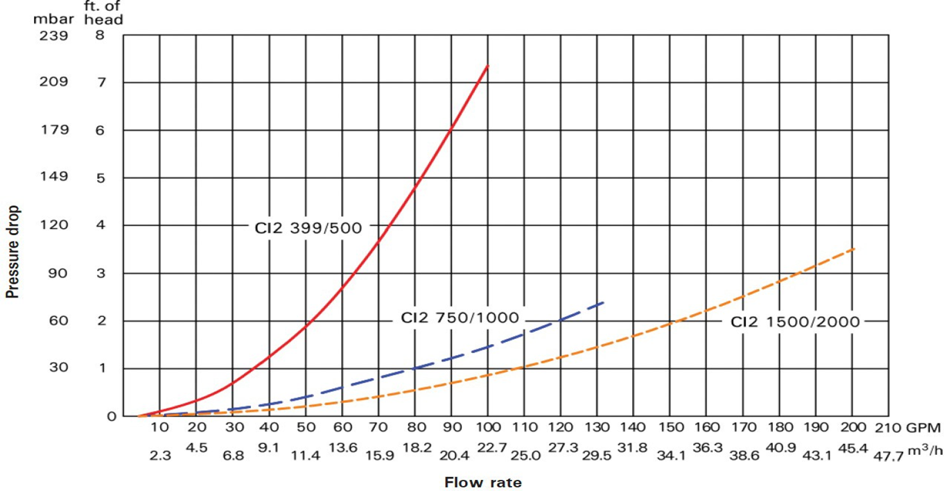
Pump Sizing:
| Primary/Secondary Pump Sizing Recommendation | ||||||||||||||||||||||||||||||||||||||||||||||||||||||||||||||||||||
 Bitmap Bitmap  Bitmap Bitmap 
|
Back to Index | |||||||||||||||||||||||||||||||||||||||||||||||||||||||||||||||||||
 |
||||||||||||||||||||||||||||||||||||||||||||||||||||||||||||||||||||
| Pump Selection Criteria ● ECM pumps are listed due to the ability to accept a 0-10 Vdc signal ● Flow rate based on a 20 °F ΔT ● Selection based on Steel Pipe ○ 70 linear ft. ○ Max Velocity of 8 ft/s ○ Max Head loss of 4 ft/ 100ft ● Pipe fitting factor of 1.5 ● Pipe size auto selected |
||||||||||||||||||||||||||||||||||||||||||||||||||||||||||||||||||||
| Boiler Model | Conditions | Taco Pump | Grundfos Pump (Magna 3) | |||||||||||||||||||||||||||||||||||||||||||||||||||||||||||||||||
| CI2-399 | 39 gpm @ 12 ft | VR 15 L or 0034e* |
Magna3 32-100 F | |||||||||||||||||||||||||||||||||||||||||||||||||||||||||||||||||
| CI2-500 | 48 gpm @ 13 ft | VR15L | Magna3 40-80F | |||||||||||||||||||||||||||||||||||||||||||||||||||||||||||||||||
| CI2 750 | 73 GPM @ 13.5 ft | VR20 M | Magna3 40-120 | |||||||||||||||||||||||||||||||||||||||||||||||||||||||||||||||||
| CI2-1000 | 97 GPM @ 11 ft | VR25L | Magna3 50-120 | |||||||||||||||||||||||||||||||||||||||||||||||||||||||||||||||||
| CI2 1500 | 146 GPM @ 10 ft | VR25H | Magna3 65-120 | |||||||||||||||||||||||||||||||||||||||||||||||||||||||||||||||||
| CI2-2000 | 194 GPM @ 13 ft | VR25H | Magna3 65-150 | |||||||||||||||||||||||||||||||||||||||||||||||||||||||||||||||||
| *Note: 33 gpm @12 ft for a 0034e Taco Pump | ||||||||||||||||||||||||||||||||||||||||||||||||||||||||||||||||||||
Gas Regulator Recommendation:
| Gas Regulator Recommendation | |||||||||||||||||||||||||||||||||||||||||||||||||||||||||||||||
|
Back to Index | ||||||||||||||||||||||||||||||||||||||||||||||||||||||||||||||
| Vented Regulators: | |||||||||||||||||||||||||||||||||||||||||||||||||||||||||||||||
| Boiler Model |
Gas Pressure |
Model | Outlet | Orifice | Spring | ||||||||||||||||||||||||||||||||||||||||||||||||||||||||||
| CI2-399 | 2 psig | B42R | 1-1/4 | 1/2x9/16" | Dk Gr (31) | ||||||||||||||||||||||||||||||||||||||||||||||||||||||||||
| 5 psig | B42R | 1-1/4 | 1/2x9/16" | Dk Gr (31) | |||||||||||||||||||||||||||||||||||||||||||||||||||||||||||
| CI2-500 | 2 psig | B31R | 1-1/4 | 1/2" | Lt Grn | ||||||||||||||||||||||||||||||||||||||||||||||||||||||||||
| 5 psig | B42R | 1-1/4 | 1/2x9/16" | Dk Gr (31) | |||||||||||||||||||||||||||||||||||||||||||||||||||||||||||
| CI2 750 | 2 psig | B34SR | 1-1/2 | 7/8" x 1" | Blk | ||||||||||||||||||||||||||||||||||||||||||||||||||||||||||
| 5 psig | B31R | 1-1/4 | 1/2" | Lt Grn | |||||||||||||||||||||||||||||||||||||||||||||||||||||||||||
| CI2-1000 | 2 psig | B34SR | 1-1/2 | 7/8" x 1" | Blk | ||||||||||||||||||||||||||||||||||||||||||||||||||||||||||
| 5 psig | B31R | 1-1/4 | 1/2" | Lt Grn | |||||||||||||||||||||||||||||||||||||||||||||||||||||||||||
| CI2- 1500 | 2 psig | B34SR | 2 | 7/8" x 1" | Blk | ||||||||||||||||||||||||||||||||||||||||||||||||||||||||||
| 5 psig | B34SR | 2 | 7/8" x 1" | Blk | |||||||||||||||||||||||||||||||||||||||||||||||||||||||||||
| CI2-2000 | 2 psig | B34R | 2 | 7/8" x 1" | Blk | ||||||||||||||||||||||||||||||||||||||||||||||||||||||||||
| 5 psig | B34SR | 2 | 7/8" x 1" | Blk | |||||||||||||||||||||||||||||||||||||||||||||||||||||||||||
| Note: Regulators are to be installed with 10 linear ft of gas piping between the regulator and boiler. Additionally, the gas pipe size between the regulator and the boiler is to be the size of the boiler gas connection. | |||||||||||||||||||||||||||||||||||||||||||||||||||||||||||||||
Typical Wiring Diagram:
PLUG 96: 5-6 - Dry Contact Enable
PLUG 1: 1-2 - Outdoor Air Sensor
All 120V Outputs are rated at 2A Max.
|

