
 168
168
CI2 Technical Service Guide Highlights
Commissioning:
| Commissioning the System with the Commissioning Assistant | ||||||||||||||||||||||||||||||||||||||||||||||||||||||||||||||||||||||||||||||||||||||||||||||||||||||||||||||||||||
| Single boiler system 1. Open the gas shut-off valve. 2. If the boiler has not been switched on yet: Turn on the ON/OFF switch. The commissioning assistant starts automatically. If the boiler has already been switched on: See chapter “Calling up the commissioning assistant at a later point”, page 15. 3. Commission the boiler and follow the commissioning assistant. See the overview below. Note: All PlusBus subscribers must be connected and switched on. Note: Depending on the type of boiler, the accessories connected and other settings, not all menu points will be displayed. Note: After the commissioning assistant has finished, check that the actuators are connected and operating correctly. Start the actuator test, refer to page 53. |
||||||||||||||||||||||||||||||||||||||||||||||||||||||||||||||||||||||||||||||||||||||||||||||||||||||||||||||||||||
| WARNING | ||||||||||||||||||||||||||||||||||||||||||||||||||||||||||||||||||||||||||||||||||||||||||||||||||||||||||||||||||||
|
To prevent flue gas escaping, only use the condensate drain with a trap. Ensure there are no leaks from the flue system. |
||||||||||||||||||||||||||||||||||||||||||||||||||||||||||||||||||||||||||||||||||||||||||||||||||||||||||||||||||||
| Commissioning assistant sequence | Explanations and references | |||||||||||||||||||||||||||||||||||||||||||||||||||||||||||||||||||||||||||||||||||||||||||||||||||||||||||||||||||
| Commissioning | ||||||||||||||||||||||||||||||||||||||||||||||||||||||||||||||||||||||||||||||||||||||||||||||||||||||||||||||||||||
| Language | Factory setting: English | |||||||||||||||||||||||||||||||||||||||||||||||||||||||||||||||||||||||||||||||||||||||||||||||||||||||||||||||||||
| With programming unit | If commissioning is to be carried out at the programming unit of the boiler. | |||||||||||||||||||||||||||||||||||||||||||||||||||||||||||||||||||||||||||||||||||||||||||||||||||||||||||||||||||
| With software tool |  The boiler automatically switches on the WiFi access point. The boiler automatically switches on the WiFi access point.Further commissioning steps according to the instructions of the software tool used (e.g. “Viguide”) Note: Apps for commissioning and service are available for iOS and Android devices. Cascade systems can only be commissioned using the software tool. |
|||||||||||||||||||||||||||||||||||||||||||||||||||||||||||||||||||||||||||||||||||||||||||||||||||||||||||||||||||
| Units of measurement | ||||||||||||||||||||||||||||||||||||||||||||||||||||||||||||||||||||||||||||||||||||||||||||||||||||||||||||||||||||
| Date and time | Set the current time. | |||||||||||||||||||||||||||||||||||||||||||||||||||||||||||||||||||||||||||||||||||||||||||||||||||||||||||||||||||
| Operating mode |
|
|||||||||||||||||||||||||||||||||||||||||||||||||||||||||||||||||||||||||||||||||||||||||||||||||||||||||||||||||||
| Gas type | If operating with LPG, switch to “LPG” (the delivered condition is Natural Gas) | |||||||||||||||||||||||||||||||||||||||||||||||||||||||||||||||||||||||||||||||||||||||||||||||||||||||||||||||||||
| Flue system type |
|
|||||||||||||||||||||||||||||||||||||||||||||||||||||||||||||||||||||||||||||||||||||||||||||||||||||||||||||||||||
| Flue length adjustment | Specification of the effective flue and ventilation air length. To determine the effective flue and ventilation air length, see page 19, chapter “Matching the burner output to the flue system”. | |||||||||||||||||||||||||||||||||||||||||||||||||||||||||||||||||||||||||||||||||||||||||||||||||||||||||||||||||||
| If no further settings are to be performed, the commissioning assistant can now be closed. | ||||||||||||||||||||||||||||||||||||||||||||||||||||||||||||||||||||||||||||||||||||||||||||||||||||||||||||||||||||
 Bitmap Bitmap  Bitmap Bitmap  |
||||||||||||||||||||||||||||||||||||||||||||||||||||||||||||||||||||||||||||||||||||||||||||||||||||||||||||||||||||
| 11 | ||||||||||||||||||||||||||||||||||||||||||||||||||||||||||||||||||||||||||||||||||||||||||||||||||||||||||||||||||||
| Commissioning | Vitocrossal 200 CI2 Service | |||||||||||||||||||||||||||||||||||||||||||||||||||||||||||||||||||||||||||||||||||||||||||||||||||||||||||||||||||
| Commissioning the System with the Commissioning Assistant (continued) | ||||||||||||||||||||||||||||||||||||||||||||||||||||||||||||||||||||||||||||||||||||||||||||||||||||||||||||||||||||
| Commissioning assistant sequence | Explanations and references | |||||||||||||||||||||||||||||||||||||||||||||||||||||||||||||||||||||||||||||||||||||||||||||||||||||||||||||||||||
| System scheme | ||||||||||||||||||||||||||||||||||||||||||||||||||||||||||||||||||||||||||||||||||||||||||||||||||||||||||||||||||||
| Heating circuit 1 | Heating circuit without mixing valve | |||||||||||||||||||||||||||||||||||||||||||||||||||||||||||||||||||||||||||||||||||||||||||||||||||||||||||||||||||
| Heating circuit 2, 3 ... | Heating circuits with mixing valve | |||||||||||||||||||||||||||||||||||||||||||||||||||||||||||||||||||||||||||||||||||||||||||||||||||||||||||||||||||
Not available Tank with one sensor Tank with one sensor and DHW recirculation pump Tank with temperature switch Tank with temperature switch and DHW recirculation pump |
Settings for DHW heating according to the system components System without DHW heating System with DHW tank with 1 tank temperature sensor System with DHW tank with 1 DHW tank temperature sensor and DHW recirculation pump System with DHW tank with temperature switch (such as an aquastat) System with DHW tank with temperature switch, (such as an aquastat) and DHW recirculation pump |
|||||||||||||||||||||||||||||||||||||||||||||||||||||||||||||||||||||||||||||||||||||||||||||||||||||||||||||||||||
Low loss header, heating only DHW heating upstream of low loss header DHW heating downstream of low loss header Buffer tank, heating only DHW heating upstream of buffer tank DHW heating downstream of buffer tank |
Settings for the consumer circuits according to the system components There is no low loss header or heating water buffer tank in the system. System with low loss header, without DHW heating DHW heating with e.g. separate DHW tank connected upstream of the low loss header DHW heating with e.g. separate DHW tank connected downstream of the low loss header System with heating water buffer tank, without DHW heating DHW heating with e.g. separate DHW tank connected upstream of the heating water buffer tank DHW heating with e.g. separate DHW tank connected downstream of the heating water buffer tank |
|||||||||||||||||||||||||||||||||||||||||||||||||||||||||||||||||||||||||||||||||||||||||||||||||||||||||||||||||||
| Heating zone/safety input Heating zone 1 |
Not available or temperature controller or safety device 1 Not available or temperature controller or safety device 2 Not available or temperature controller or safety device 3 |
|||||||||||||||||||||||||||||||||||||||||||||||||||||||||||||||||||||||||||||||||||||||||||||||||||||||||||||||||||
Heating zone 3 (based on boiler application type) |
||||||||||||||||||||||||||||||||||||||||||||||||||||||||||||||||||||||||||||||||||||||||||||||||||||||||||||||||||||
| 12 | ||||||||||||||||||||||||||||||||||||||||||||||||||||||||||||||||||||||||||||||||||||||||||||||||||||||||||||||||||||
| Vitocrossal 200 CI2 Service | Commissioning | |||||||||||||||||||||||||||||||||||||||||||||||||||||||||||||||||||||||||||||||||||||||||||||||||||||||||||||||||||
| Commissioning the System with the Commissioning Assistant (continued) | ||||||||||||||||||||||||||||||||||||||||||||||||||||||||||||||||||||||||||||||||||||||||||||||||||||||||||||||||||||
| Commissioning assistant sequence | Explanations and references | |||||||||||||||||||||||||||||||||||||||||||||||||||||||||||||||||||||||||||||||||||||||||||||||||||||||||||||||||||
| Floating contact: Function selection plug 96 | If a contact has been connected to plug 96. | |||||||||||||||||||||||||||||||||||||||||||||||||||||||||||||||||||||||||||||||||||||||||||||||||||||||||||||||||||
External demand, DHW circulation pump External demand (based on boiler application type) External blocking Heat demand (based on boiler application type) |
Push button function, DHW recirculation pump runs for 5 min. Boiler demand with adjustable target supply temperature (parameter 528.0) and target primary pump speed (parameter 1100.2) Call for heat is shown in the display/menu as “Heating zone 4”. |
|||||||||||||||||||||||||||||||||||||||||||||||||||||||||||||||||||||||||||||||||||||||||||||||||||||||||||||||||||
| EM-EA1 (DIO): Function selection (based on boiler application type) |
If an EM-EA1 extension (DIO electronics module) is connected as a function extension. | |||||||||||||||||||||||||||||||||||||||||||||||||||||||||||||||||||||||||||||||||||||||||||||||||||||||||||||||||||
| Functions | Selection of the connected function according to the table in the EM-EA1 exten- sion installation instructions. | |||||||||||||||||||||||||||||||||||||||||||||||||||||||||||||||||||||||||||||||||||||||||||||||||||||||||||||||||||
| Remote control units | ||||||||||||||||||||||||||||||||||||||||||||||||||||||||||||||||||||||||||||||||||||||||||||||||||||||||||||||||||||
| Set the type of remote control and subscriber no. as assignment to the respective heating circuit. Up to 4 heating circuits can be assigned to one remote control unit. It is not possible for several remote controls to act on one heating circuit. | ||||||||||||||||||||||||||||||||||||||||||||||||||||||||||||||||||||||||||||||||||||||||||||||||||||||||||||||||||||
| “Primary pump” | ||||||||||||||||||||||||||||||||||||||||||||||||||||||||||||||||||||||||||||||||||||||||||||||||||||||||||||||||||||
|
On/off control 0 - 10V modulation control |
|||||||||||||||||||||||||||||||||||||||||||||||||||||||||||||||||||||||||||||||||||||||||||||||||||||||||||||||||||
| Maintenance | ||||||||||||||||||||||||||||||||||||||||||||||||||||||||||||||||||||||||||||||||||||||||||||||||||||||||||||||||||||
| Interval in burner hours run until next maintenance | Interval adjustable in steps of 100 h. | |||||||||||||||||||||||||||||||||||||||||||||||||||||||||||||||||||||||||||||||||||||||||||||||||||||||||||||||||||
| Interval until next maintenance | Interval adjustable to 3, 6, 12, 18 or 24 months. | |||||||||||||||||||||||||||||||||||||||||||||||||||||||||||||||||||||||||||||||||||||||||||||||||||||||||||||||||||
| Multi boiler system The lead boiler must be commissioned using the Viguide app (service layer). Note: Commission the lead boiler first, then the lag boilers. The lag boiler is numbered by manually setting the subscriber number (ID). Always enter the ID number consecutively and without gaps! After this, the respective boiler has to be commissioned using the Viguide app. Follow the instructions in the app and establish a connection between the lead boiler and the Viguide app. |
||||||||||||||||||||||||||||||||||||||||||||||||||||||||||||||||||||||||||||||||||||||||||||||||||||||||||||||||||||
| Bitmap Bitmap |
||||||||||||||||||||||||||||||||||||||||||||||||||||||||||||||||||||||||||||||||||||||||||||||||||||||||||||||||||||
| 13 | ||||||||||||||||||||||||||||||||||||||||||||||||||||||||||||||||||||||||||||||||||||||||||||||||||||||||||||||||||||
| Commissioning | Vitocrossal 200 CI2 Service | |||||||||||||||||||||||||||||||||||||||||||||||||||||||||||||||||||||||||||||||||||||||||||||||||||||||||||||||||||
| Commissioning the System with the Commissioning Assistant (continued) | ||||||||||||||||||||||||||||||||||||||||||||||||||||||||||||||||||||||||||||||||||||||||||||||||||||||||||||||||||||
| Commissioning assistant sequence | Explanations and references | |||||||||||||||||||||||||||||||||||||||||||||||||||||||||||||||||||||||||||||||||||||||||||||||||||||||||||||||||||
| Commissioning | ||||||||||||||||||||||||||||||||||||||||||||||||||||||||||||||||||||||||||||||||||||||||||||||||||||||||||||||||||||
| Viguide function type: | Lead 1 (1) Cascade lead without heat provides cascade functionalities to connected lag devices. Does not support DHW or heat supply by itself. Lead 1 (1) Cascade heat lead provides cascade functionalities to its own and connected lag devices. Does not support DHW supply or global DHW supply. Lead 1 (1) Cascade heat DHW lead provides cascade functionalities to its own and connected lag devices and provides local DHW production. Lag 1-15 (2-16) Heat lag is a device controller that provides lag heating device functionalities Lag 1-15 (2-16) Buffer lag to be applied for multivalent systems, e.g. CHP Lag 1-15 (2-16) DHW lag is a lag device that provides only support in DHW production – hydraulically separated Lag 1-15 (2-16) Backup heater is a lag device that is taken out of the cascade sequence as a fall-back solution, central heating only.. |
|||||||||||||||||||||||||||||||||||||||||||||||||||||||||||||||||||||||||||||||||||||||||||||||||||||||||||||||||||
| Viguide cascade member se- quencing strategy: | 1.1 Dynamic strategy – fixed first dynamic sequence of the cascade members with manually configured fixed first device in sequence 1.2 Dynamic strategy – fixed last dynamic sequence of the cascade members with manually configured fixed last device in sequence 1.3 Dynamic strategy – runtime optimization dynamic sequence of the cascade members with runtime optimization of the cascade members 2 Manual mode – manual mode of the cascade members with fixed configured sequence. In general the whole cascade is supply temperature-controlled: A particular supply temperature is requested from all cascade members. |
|||||||||||||||||||||||||||||||||||||||||||||||||||||||||||||||||||||||||||||||||||||||||||||||||||||||||||||||||||
| Commissioning assistant sequence | Explanations and references | |||||||||||||||||||||||||||||||||||||||||||||||||||||||||||||||||||||||||||||||||||||||||||||||||||||||||||||||||||
| Viguide lead boiler commissioning: |  Units: Units:Gas type Altitude Filling Venting Safety functions on MZIO; low gas pressure via ZI2; high gas pressure via ZI3). Central heating pump mode (auto or modulation controlled pump). Set up the combustion air interface. Flue gas sensor test. Time and auto summer/wintertime. DHW function: one-time load, hygiene function and scald protection. Supported number and type (direct/mixed/none) of heating circuits. Number of TT circuits. Function of TT circuits. Control type (weather-compensated/constant control) – if weather- compensated, then the setting “heating and TT circuit” or only “heating” without TT circuit is selectable. Setup of internet connection If weather-compensated, then source of valid outside air temperature is selectable. If constant mode control type: a) Constant flow control for heating circuits. b) Constant flow control with data interface for gateway/building automation system for heating circuits. c) Fixed temperature supply to TT zones with TT circuits is selectable. |
|||||||||||||||||||||||||||||||||||||||||||||||||||||||||||||||||||||||||||||||||||||||||||||||||||||||||||||||||||
| 14 | ||||||||||||||||||||||||||||||||||||||||||||||||||||||||||||||||||||||||||||||||||||||||||||||||||||||||||||||||||||
| Vitocrossal 200 CI2 Service | Commissioning | |||||||||||||||||||||||||||||||||||||||||||||||||||||||||||||||||||||||||||||||||||||||||||||||||||||||||||||||||||
| Commissioning the System with the Commissioning Assistant (continued) | ||||||||||||||||||||||||||||||||||||||||||||||||||||||||||||||||||||||||||||||||||||||||||||||||||||||||||||||||||||
| Commissioning assistant sequence | Explanations and references | |||||||||||||||||||||||||||||||||||||||||||||||||||||||||||||||||||||||||||||||||||||||||||||||||||||||||||||||||||
| Viguide lag boiler commissioning: |
Gas type Altitude Filling Purging Safety functions on MZIO; low gas pressure via ZI2; high gas pressure via ZI3). Central heating pump mode (auto or modulation controlled pump). Set up the combustion air interface. Flue gas sensor test. |
|||||||||||||||||||||||||||||||||||||||||||||||||||||||||||||||||||||||||||||||||||||||||||||||||||||||||||||||||||
| Viguide service layer lead device: |
System configuration: General – device/boiler – DHW – heating circuit 1/2/3/4 - TT circuits Diagnosis: General – device/burner – DHW – heating circuit - TT circuits |
|||||||||||||||||||||||||||||||||||||||||||||||||||||||||||||||||||||||||||||||||||||||||||||||||||||||||||||||||||
| Viguide service layer lag device: |
System configuration: General – device/boiler Diagnosis: General – device/burner |
|||||||||||||||||||||||||||||||||||||||||||||||||||||||||||||||||||||||||||||||||||||||||||||||||||||||||||||||||||
Bitmap Bitmap Bitmap  Bitmap Bitmap  |
||||||||||||||||||||||||||||||||||||||||||||||||||||||||||||||||||||||||||||||||||||||||||||||||||||||||||||||||||||
|
Switching internet connectivity on/off
|
Switch on the WiFi connection or LAN and establish a connection to the router. Activating the internet connection: Calling up the commissioning assistant at a later point If you need to continue commissioning later, the commissioning assistant can be reactivated at any time. Tap the following buttons: 1. 2. “Service” 3. Enter password “viservice”. 4. Confirm with . 5. “Commissioning” |
|||||||||||||||||||||||||||||||||||||||||||||||||||||||||||||||||||||||||||||||||||||||||||||||||||||||||||||||||||
 |
||||||||||||||||||||||||||||||||||||||||||||||||||||||||||||||||||||||||||||||||||||||||||||||||||||||||||||||||||||


Heating Curve Adjustment:
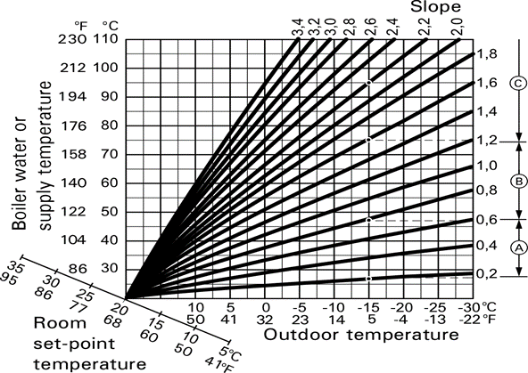
Example for outdoor temperature 5°F (−15°C)
A. Underfloor heating system, slope 0.2 to 0.8
B. Low temperature heating system, slope 0.8 to 1.6
C. Heating systems with a boiler water temperature in
excess of 167°F (75°C), slope greater than 1.6
|
Tap the following buttons:
|
Gas Pressure Supply:
Supply pressure for NG/LPG
1. Start the burner.
Note: Switch the burner to maximum heating output.
For this, activate the emissions test switch at the
boiler control unit.
2. Measure the supply pressure (running pressure).
Use suitable measuring instruments calibrated with
a minimum resolution of 0.04 “w.c. Value must be as
per the chart below:
| Supply pressure with: | Corrective action | |||||||||||||||||||||||||||||||||||||||||||||||||||||||||||||||
| Natural gas | Liquid propane gas | |||||||||||||||||||||||||||||||||||||||||||||||||||||||||||||||
| under 4 ”w.c. | under 10 ”w.c. | Do not attempt adjustment. Call local gas utility | ||||||||||||||||||||||||||||||||||||||||||||||||||||||||||||||
| 4 to 14 “w.c. | 10 to 14 ”w.c. | Start up boiler. | ||||||||||||||||||||||||||||||||||||||||||||||||||||||||||||||
| over 14 ”w.c | over 14 ”w.c. | Do not attempt adjustment. Call local gas utility to decrease pressure. Boiler valve must not be exposed to pressure over 14 ”w.c. | ||||||||||||||||||||||||||||||||||||||||||||||||||||||||||||||
Note: The supply pressure should be between 4 “w.c.
and 14 ”w.c. for NG and 10” w.c. to 14” w.c.
for LPG. The gas pressure switch for the inlet
pressure test/check is factory set to 4 ”w.c.
Never alter this setting.
3. Record the actual value in the maintenance record
(on page 83).
4. Close the gas shut-off valve.
5. Remove the pressure tester and close test nipple .
Error Codes For CI2 Series Boiler:
| Vitocrossal 200 CI2 Service Troubleshooting Calling up Fault Messages from the Fault Memory (message history) |
|||||||||||||||||||||||||||||||||||||||||||||||||||||||||||||||||||||||||||||||||
| The 10 most recent faults (including those remedied) and maintenance messages are saved and can be called up. Faults are sorted by date. Tap the following buttons: 1. “ “ 2. “Service” 3. Enter password “viservice”. 4. 5. “Message history” 6. “Faults” to call up saved fault messages. 7. If you wish to delete the list, tap . 8. Confirm with . Fault Messages Note: Fault messages dependent on boiler equipment level, and connected accessories. |
|||||||||||||||||||||||||||||||||||||||||||||||||||||||||||||||||||||||||||||||||
| Displayed fault code | System characteristics | Cause | Measures | ||||||||||||||||||||||||||||||||||||||||||||||||||||||||||||||||||||||||||||||
| F.7 | No DHW heating | Lead break, tank temperature sensor |
Check tank temperature sensor. Measure voltage at sensor input on electronics module. Target value: 3.3V– with sensor disconnected Replace faulty component if necessary. |
||||||||||||||||||||||||||||||||||||||||||||||||||||||||||||||||||||||||||||||
| F.8 | No DHW heating | Short circuit, tank temperature sensor | Check tank temperature sensor. Replace faulty component if necessary. | ||||||||||||||||||||||||||||||||||||||||||||||||||||||||||||||||||||||||||||||
| F.13 | Regulates as if the outside temperature were 32°F (0°C). | Lead break, outside temperature sensor |
Check outside temperature sensor and connection to sensor. Measure voltage at sensor input on electronics module. Target value: 3.3V– with sensor disconnected Replace faulty component if necessary. |
||||||||||||||||||||||||||||||||||||||||||||||||||||||||||||||||||||||||||||||
| F.14 | Regulates as if the outside temperature were 32°F (0°C). | Short circuit, outside temperature sensor | Check outside temperature sensor and connection to sensor. Replace faulty components if necessary. | ||||||||||||||||||||||||||||||||||||||||||||||||||||||||||||||||||||||||||||||
|
|||||||||||||||||||||||||||||||||||||||||||||||||||||||||||||||||||||||||||||||||
| 57 | |||||||||||||||||||||||||||||||||||||||||||||||||||||||||||||||||||||||||||||||||
| Troubleshooting | Vitocrossal 200 CI2 Service | ||||||||||||||||||||||||||||||||||||||||||||||||||||||||||||||||||||||||||||||||
| Fault Messages (continued) | |||||||||||||||||||||||||||||||||||||||||||||||||||||||||||||||||||||||||||||||||
| Displayed fault code | System characteristics | Cause | Measures | ||||||||||||||||||||||||||||||||||||||||||||||||||||||||||||||||||||||||||||||
| F.29 | Regulates without supply temperature sensor for low loss header. | Lead break, low loss header sensor |
Check supply temperature sensor, low loss header. Measure voltage at sensor input on electronics module. Target value: 3.3V– with sensor disconnected |
||||||||||||||||||||||||||||||||||||||||||||||||||||||||||||||||||||||||||||||
| F.30 | Regulates without supply temperature sensor for low loss header. | Short circuit, low loss header sensor | Check supply temperature sensor, low loss header. Measure voltage at sensor input on electronics module. Target value: 3.3V– with sensor disconnected |
||||||||||||||||||||||||||||||||||||||||||||||||||||||||||||||||||||||||||||||
| F.49 | Burner in a fault state | Lead break, flue gas temperature sensor | Check flue gas temperature sensor. Reset the boiler. | ||||||||||||||||||||||||||||||||||||||||||||||||||||||||||||||||||||||||||||||
| F.50 | Burner in a fault state | Short circuit, flue gas temperature sensor | Check flue gas temperature sensor. Reset the boiler. | ||||||||||||||||||||||||||||||||||||||||||||||||||||||||||||||||||||||||||||||
| F.57 | Normal operation without room influence | Lead break, room temperature sensor |
Check plug and cable of external room temperature sensor, heating circuit. If no external room temperature sensor installed, replace Vitotrol programming unit. |
||||||||||||||||||||||||||||||||||||||||||||||||||||||||||||||||||||||||||||||
| F.58 | Normal operation without room influence | Short circuit, room temperature sensor | Check plug and cable of external room temperature sensor, heating circuit. If no external room temperature sensor installed, replace Vitotrol programming unit. |
||||||||||||||||||||||||||||||||||||||||||||||||||||||||||||||||||||||||||||||
| F.59 | Burner locked out | Power supply, low voltage | Check mains voltage. If voltage is correct and the fault occurs repeatedly, replace the fan unit. |
||||||||||||||||||||||||||||||||||||||||||||||||||||||||||||||||||||||||||||||
| F.62 | Burner in a fault state | High limit safety cut-out has responded. |
Check pre-charge pressure in diaphragm expansion tank. Adjust to required system pressure. Check whether flow rate is sufficient (flow sensor and circulation pump). Reset the boiler. |
||||||||||||||||||||||||||||||||||||||||||||||||||||||||||||||||||||||||||||||
| F.63 | Burner in a fault state | Flue gas temperature limiter has responded. |
Check pre-charge pressure in diaphragm expansion tank. Adjust to required system pressure. Check whether flow rate is sufficient (flow sensor and circulation pump). Vent the system. Reset the boiler once the flue system has cooled down. |
||||||||||||||||||||||||||||||||||||||||||||||||||||||||||||||||||||||||||||||
| 58 | |||||||||||||||||||||||||||||||||||||||||||||||||||||||||||||||||||||||||||||||||
| Vitocrossal 200 CI2 Service | Troubleshooting | ||||||||||||||||||||||||||||||||||||||||||||||||||||||||||||||||||||||||||||||||
| Fault Messages (continued) | |||||||||||||||||||||||||||||||||||||||||||||||||||||||||||||||||||||||||||||||||
| Displayed fault code | System characteristics | Cause | Measures | ||||||||||||||||||||||||||||||||||||||||||||||||||||||||||||||||||||||||||||||
| F.64 | Normal operation; burner restarts | Flame loss during stabilization or operating phase. |  Check ionization electrode (replace if necessary): Check the electrode for contamination and clearance to the burner gauze assembly. Check ionization electrode (replace if necessary): Check the electrode for contamination and clearance to the burner gauze assembly. |
||||||||||||||||||||||||||||||||||||||||||||||||||||||||||||||||||||||||||||||
| F.65 | Burner in a fault state | Flame signal is not present or insufficient at burner start. | Check ventilation air/flue system and condensate drain; clean if necessary. Check ionization electrode and connecting cable. Check the ignition. Check the connecting cables between the ignition module and ignition electrode; check the ignition electrode for clearance, contamination and broken insulation. |
||||||||||||||||||||||||||||||||||||||||||||||||||||||||||||||||||||||||||||||
| F.67 | Burner in a fault state | Ionization current lies outside the permissible range |
Check ionization electrode: Clearance to burner gauze assembly Check electrode/burner gauze assembly for contamination. If specified measures don’t help, replace fan unit. Reset the boiler. |
||||||||||||||||||||||||||||||||||||||||||||||||||||||||||||||||||||||||||||||
| F.69 | Burner in a fault state | Ionization current lies outside the permissible range |
Check whether insulation block is touching electrode ceramic. Check gas solenoid valve: Activate “Minimum heating output” for approx. 4 min in actuator test. If this causes a fault to occur, replace BCU burner control unit. In the actuator test, switch from “Minimum heating output” to “Maximum heating output”. If this fault occurs during modulation, check the intake screen for contamination. Replace the fan unit if necessary. |
||||||||||||||||||||||||||||||||||||||||||||||||||||||||||||||||||||||||||||||
| F.71 | Burner in a fault state | Fan speed too low |
Check the gas type and flue system setting in the commissioning assistant and correct if necessary. Reset the boiler. |
||||||||||||||||||||||||||||||||||||||||||||||||||||||||||||||||||||||||||||||
| F.72 | Burner in a fault state | Fan idle state not reached | Reset the boiler. If fault occurs repeatedly, replace fan unit. |
||||||||||||||||||||||||||||||||||||||||||||||||||||||||||||||||||||||||||||||
| F.74 | Burner locked out. Internal circulation pump off. No central heating and no DHW heating. |
System pressure too low |
If the fault occurs repeatedly: Check system pressure sensor with external pressure gauge. Check diaphragm expansion tank pre-charge pressure. Check settings for target system pressure and range. |
||||||||||||||||||||||||||||||||||||||||||||||||||||||||||||||||||||||||||||||
| 59 | |||||||||||||||||||||||||||||||||||||||||||||||||||||||||||||||||||||||||||||||||
| Troubleshooting | Vitocrossal 200 CI2 Service | ||||||||||||||||||||||||||||||||||||||||||||||||||||||||||||||||||||||||||||||||
| Fault Messages (continued) | |||||||||||||||||||||||||||||||||||||||||||||||||||||||||||||||||||||||||||||||||
| Displayed fault code | System characteristics | Cause | Measures | ||||||||||||||||||||||||||||||||||||||||||||||||||||||||||||||||||||||||||||||
| F.77 | Burner in a fault state | Data memory burner control unit | Reset the boiler. If the fault recurs, replace the BCU burner control unit. |
||||||||||||||||||||||||||||||||||||||||||||||||||||||||||||||||||||||||||||||
| F.87 | Burner in a fault state | Water pressure too high |
Replace the safety assembly. Open BDF valves. Check expansion vessel function. Correct the amount of water in the system. |
||||||||||||||||||||||||||||||||||||||||||||||||||||||||||||||||||||||||||||||
| F.89 | No central heating and no DHW heating | Circulation pump blocked | Check circulation pump. Replace if necessary. | ||||||||||||||||||||||||||||||||||||||||||||||||||||||||||||||||||||||||||||||
| F.91 | Function of affected extension in emergency mode | DIO electronics module communication error | Check connections to DIO electronics module and connection to heat management unit. | ||||||||||||||||||||||||||||||||||||||||||||||||||||||||||||||||||||||||||||||
| F.92 | Function of the relevant electronics module in emergency mode | ADIO electronics module communication error |
Check connections and leads to the ADIO electronics module. Check PlusBus voltage level (24 to 28V). Check subscriber number on rotary switch S1 and correct if necessary. |
||||||||||||||||||||||||||||||||||||||||||||||||||||||||||||||||||||||||||||||
| F.94 | Function of the relevant electronics module in emergency mode | Function of the relevant electronics module in emergency mode |
Check connections and leads to the SDIO electronics module. Check PlusBus voltage level (24-28V). |
||||||||||||||||||||||||||||||||||||||||||||||||||||||||||||||||||||||||||||||
| F.99 | Electronics modules connected to PlusBus not functioning | Communication error PlusBus |
Check the connecting elements (plugs) for firm seating and corrosion. Check for connection of an incorrect device; refer to the connection diagram/installation instructions. After checking, reset the power supply to the system and check whether the fault recurs. If the fault recurs after the burner control unit has been restarted, replace the burner control unit concerned. |
||||||||||||||||||||||||||||||||||||||||||||||||||||||||||||||||||||||||||||||
| F.100 | Electronics modules connected to PlusBus not functioning | Voltage error PlusBus | Check whether the PlusBus power supply on the HMU heat management unit is OK: Remove all connected PlusBus components and reconnect one by one. Check that there aren’t more than 2 Vitotrol 200-E connected to the HMU. Check whether there is a short circuit at the PlusBus cable. Check the PlusBus voltage. |
||||||||||||||||||||||||||||||||||||||||||||||||||||||||||||||||||||||||||||||
| 60 | |||||||||||||||||||||||||||||||||||||||||||||||||||||||||||||||||||||||||||||||||
| Vitocrossal 200 CI2 Service | Troubleshooting | ||||||||||||||||||||||||||||||||||||||||||||||||||||||||||||||||||||||||||||||||
| Fault Messages (continued) | |||||||||||||||||||||||||||||||||||||||||||||||||||||||||||||||||||||||||||||||||
| Displayed fault code | System characteristics | Cause | Measures | ||||||||||||||||||||||||||||||||||||||||||||||||||||||||||||||||||||||||||||||
| F.104 | Depending on configuration of EM-EA1 extension (DIO electronics module) |
External fault message input active | Check connected external device. | ||||||||||||||||||||||||||||||||||||||||||||||||||||||||||||||||||||||||||||||
| F.142 | Burner in a fault state | Communication error CAN bus |
If the fault still persists, visually check the plug-in connections and cables of the CAN bus. Check further CAN bus subscribers. If fault still persists, replace the fan unit. |
||||||||||||||||||||||||||||||||||||||||||||||||||||||||||||||||||||||||||||||
| F.160 | Burner in a fault state | Communication error CAN bus |
If only F.160 is displayed, check the connections of the external CAN bus subscribers. Check the connecting cables for firm seating and corrosion. Reset the boiler. |
||||||||||||||||||||||||||||||||||||||||||||||||||||||||||||||||||||||||||||||
| F.180 | Burner in a fault state | Gas pressure too low |
Check whether the gas pressure switch is working properly. Replace the gas fitting if necessary Direct replacement of the gas pressure switch is not permissible. |
||||||||||||||||||||||||||||||||||||||||||||||||||||||||||||||||||||||||||||||
| F.182 | No DHW heating | Short circuit, outlet temperature sensor (if installed) | Check outlet temperature sensor (plug X1, cores 13 and 14). Measure sensor input on electronics module. Target value: 3.3V– with sensor disconnected |
||||||||||||||||||||||||||||||||||||||||||||||||||||||||||||||||||||||||||||||
| F.183 | No DHW heating | Lead break, outlet temperature sensor (if installed) | Check the outlet temperature sensor. | ||||||||||||||||||||||||||||||||||||||||||||||||||||||||||||||||||||||||||||||
| F.185 | Burner in a fault state | Lead break, supply temperature sensor/high limit safety cut-out | Check the supply temperature sensor/ high limit safety cut-out. Check sensor lead. Replace faulty component if necessary. Reset the boiler. | ||||||||||||||||||||||||||||||||||||||||||||||||||||||||||||||||||||||||||||||
| F.299 | Time/date incorrect | Real time clock setting incorrect | Set the time and date. | ||||||||||||||||||||||||||||||||||||||||||||||||||||||||||||||||||||||||||||||
| F.342 | No central heating, no DHW heating | Communication error, BCU burner control unit |
Check all plug-in connections and cables of the internal CAN. Remove all plugs except X4, X2, X16 and X18 from the BCU burner control unit. Check whether fault persists. Note: Several other fault messages will be added due to the removed plugs. Ignore these. If fault message F.342 is no longer shown, reinsert the plugs one by one and establish which component is faulty. Reset the boiler. |
||||||||||||||||||||||||||||||||||||||||||||||||||||||||||||||||||||||||||||||
| 61 | |||||||||||||||||||||||||||||||||||||||||||||||||||||||||||||||||||||||||||||||||
| Troubleshooting | Vitocrossal 200 CI2 Service | ||||||||||||||||||||||||||||||||||||||||||||||||||||||||||||||||||||||||||||||||
| Fault Messages (continued) | |||||||||||||||||||||||||||||||||||||||||||||||||||||||||||||||||||||||||||||||||
| Displayed fault code | System characteristics | Cause | Measures | ||||||||||||||||||||||||||||||||||||||||||||||||||||||||||||||||||||||||||||||
| F.343 | Regulates without return temperature sensor for low loss header |
Short circuit of the common return sensor |
Check return temperature sensor for low loss header. Measure sensor input on electronics module. (3.3V– with sensor disconnected) |
||||||||||||||||||||||||||||||||||||||||||||||||||||||||||||||||||||||||||||||
| F.344 | Regulates without return temperature sensor for low loss header |
Lead break of the common return sensor |  Check return temperature sensor for low loss header. Measure sensor input on electronics module. Check return temperature sensor for low loss header. Measure sensor input on electronics module.(3.3V– with sensor disconnected) |
||||||||||||||||||||||||||||||||||||||||||||||||||||||||||||||||||||||||||||||
| F.348 | Burner in a fault state | Gas modulation valve | If several boilers are connected to a common flue system: Check whether “Multiple connections” is set in the commissioning assistant. Check the flue system for unrestricted flow. If the fault persists, replace the gas fan unit. |
||||||||||||||||||||||||||||||||||||||||||||||||||||||||||||||||||||||||||||||
| F.353 | Burner shutdown with restart if demand exists | Insufficient gas supply, burner output reduced | Check the gas supply. Optically check input-side screen in the gas solenoid valve for contamination. Reset the boiler. |
||||||||||||||||||||||||||||||||||||||||||||||||||||||||||||||||||||||||||||||
| F.354 | Burner in a fault state | Gas modulation valve tolerance outside permissible range | Replace gas fan unit. | ||||||||||||||||||||||||||||||||||||||||||||||||||||||||||||||||||||||||||||||
| F.365 | Burner in a fault state | Gas fitting relay monitoring has responded | Start the burner several times; replace the burner control unit if necessary. | ||||||||||||||||||||||||||||||||||||||||||||||||||||||||||||||||||||||||||||||
| F.370 | Burner in a fault state | Fuel valve or modulation valve will not close. | Reset the boiler. If fault occurs repeatedly, replace fan unit. |
||||||||||||||||||||||||||||||||||||||||||||||||||||||||||||||||||||||||||||||
| F.379 | Burner in a fault state | Flame signal not present or insufficient |
Check ionization electrode; replace if necessary. Reset the boiler. |
||||||||||||||||||||||||||||||||||||||||||||||||||||||||||||||||||||||||||||||
| F.380 | Burner in a fault state | Flame loss immediately after flame formation (during safety time) |
Check ionization electrode and burner gauze assembly: Clearance to burner gauze assembly Contamination on electrode Reset the boiler. |
||||||||||||||||||||||||||||||||||||||||||||||||||||||||||||||||||||||||||||||
| 62 | |||||||||||||||||||||||||||||||||||||||||||||||||||||||||||||||||||||||||||||||||
| Vitocrossal 200 CI2 Service | Troubleshooting | ||||||||||||||||||||||||||||||||||||||||||||||||||||||||||||||||||||||||||||||||
| Fault Messages (continued) | |||||||||||||||||||||||||||||||||||||||||||||||||||||||||||||||||||||||||||||||||
| Displayed fault code | System characteristics | Cause | Measures | ||||||||||||||||||||||||||||||||||||||||||||||||||||||||||||||||||||||||||||||
| F.415 | System in a fault state | Communication error of M bus gateway | Check the control cable and power supply. | ||||||||||||||||||||||||||||||||||||||||||||||||||||||||||||||||||||||||||||||
| F.416 | Burner locked out | Flue gas temperature sensor incorrectly positioned | Fit flue gas temperature sensor correctly. See “Repairs”. Carry out mains reset after fault has been remedied. |
||||||||||||||||||||||||||||||||||||||||||||||||||||||||||||||||||||||||||||||
| F.425 | System operating normally; calculation not working | Time synchronization failed | Set the time. If external time is used, check parameters 1504 and 508. | ||||||||||||||||||||||||||||||||||||||||||||||||||||||||||||||||||||||||||||||
| F.430 | Normal operation in line with target values of boiler | Communication error gateway | Check gateway module connecting cable and power supply. | ||||||||||||||||||||||||||||||||||||||||||||||||||||||||||||||||||||||||||||||
| F.517 | Normal operation, remote con- trol unit not functioning | Lead break, PlusBus cable, incorrect boiler address set, remote control faulty |
Check remote control cable. Check remote control subscriber number. Replace faulty remote control if applicable. |
||||||||||||||||||||||||||||||||||||||||||||||||||||||||||||||||||||||||||||||
| F.519 | Communication with the building management system is not possible. External control is not possible. The boiler returns to the internal control target values. |
Communication error BACnet. Same device ID twice in the same network. | Check the connecting cable and power supply to the WAGO gateway. Check the BACnet participants. |
||||||||||||||||||||||||||||||||||||||||||||||||||||||||||||||||||||||||||||||
| F.520 | Communication with the building management system is not possible. External control is not possible. The boiler returns to the internal control target values. |
Communication error Modbus. 2 identical device IDs in the same network | Check the connecting cable and power supply to the WAGO gateway. Check the Modbus participants. |
||||||||||||||||||||||||||||||||||||||||||||||||||||||||||||||||||||||||||||||
| F.527 | Burner in a fault state | Incorrect parameter set, HMU heat management unit | Overwrite (flash) the HMU heat management unit with the correct parameter set. | ||||||||||||||||||||||||||||||||||||||||||||||||||||||||||||||||||||||||||||||
| F.528 | Burner in a fault state | Incorrect parameter set, BCU burner control unit | Overwrite (flash) the BCU burner control unit with the correct parameter set. | ||||||||||||||||||||||||||||||||||||||||||||||||||||||||||||||||||||||||||||||
| F.542 | Emergency function operating mode is activated for heating circuit 1: Heating circuit pump is switched on Heating circuit mixing valve is moved to the CLOSED position |
Lead break, supply temperature sensor, heating circuit 1, incorrect setting during commissioning | Check supply temperature sensor, mixing valve 1. Measure sensor input on electronics module. (3.3V– with sensor disconnected) Check commissioning assistant setting. Check setting of ADIO rotary switch |
||||||||||||||||||||||||||||||||||||||||||||||||||||||||||||||||||||||||||||||
| F.543 | Emergency function operating mode is activated for heating circuit 1: Heating circuit pump is switched on. Heating circuit mixing valve is moved to the CLOSED position. |
Short circuit, supply temperature sensor, heating circuit 1 | Check supply temperature sensor, mixing valve 1. Measure sensor input on electronics module. (3.3V– with sensor disconnected) |
||||||||||||||||||||||||||||||||||||||||||||||||||||||||||||||||||||||||||||||
| 63 | |||||||||||||||||||||||||||||||||||||||||||||||||||||||||||||||||||||||||||||||||
| Troubleshooting | Vitocrossal 200 CI2 Service | ||||||||||||||||||||||||||||||||||||||||||||||||||||||||||||||||||||||||||||||||
| Fault Messages (continued) | |||||||||||||||||||||||||||||||||||||||||||||||||||||||||||||||||||||||||||||||||
| Displayed fault code | System characteristics | Cause | Measures | ||||||||||||||||||||||||||||||||||||||||||||||||||||||||||||||||||||||||||||||
| F.544 | Mixing valve closes. Heating circuit pump is operational. | Lead break, supply temperature sensor, heating circuit 2 with mixing valve Incorrect setting during commissioning |
Check supply temperature sensor, mixing valve 2. Measure voltage at sensor input on electronics module. Target value: 3.3V– with sensor disconnected. Check commissioning assistant setting. Checking setting of ADIO rotary switch. |
||||||||||||||||||||||||||||||||||||||||||||||||||||||||||||||||||||||||||||||
| F.545 | Mixing valve closes. Heating circuit pump is operational. | Short circuit, supply temperature sensor for heating circuit 2 with mixing valve | Check supply temperature sensor, mixing valve 2. Measure voltage at sensor input on electronics module. Target value: 3.3V– with sensor disconnected |
||||||||||||||||||||||||||||||||||||||||||||||||||||||||||||||||||||||||||||||
| F.546 | Mixing valve closes. Heating circuit pump is operational. | Lead break, supply temperature sensor, heating circuit 3 with mixing valve | Check supply temperature sensor, mixing valve 3. Measure voltage at sensor input on electronics module. Target value: 3.3V– with sensor disconnected. Check commissioning assistant setting. Checking setting of ADIO rotary switch. |
||||||||||||||||||||||||||||||||||||||||||||||||||||||||||||||||||||||||||||||
| F.547 | Mixing valve closes. Heating circuit pump is operational. | Short circuit, supply temperature sensor for heating circuit 3 with mixing valve | Check supply temperature sensor, mixing valve 3. Measure voltage at sensor input on electronics module. Target value: 3.3V– with sensor disconnected |
||||||||||||||||||||||||||||||||||||||||||||||||||||||||||||||||||||||||||||||
| F.548 | Mixing valve closes. Heating circuit pump is operational. | Short circuit, supply temperature sensor for heating circuit 4 with mixing valve |
Measure voltage at sensor input on electronics module. Target value: 3.3V– with sensor disconnected Check commissioning assistant setting. Checking setting of ADIO rotary switch. |
||||||||||||||||||||||||||||||||||||||||||||||||||||||||||||||||||||||||||||||
| F.549 | Mixing valve closes. Heating circuit pump is operational. | Short circuit, supply temperature sensor for heating circuit 4 with mixing valve | Check supply temperature sensor, mixing valve 4. Measure voltage at sensor input on electronics module. Target value: 3.3V– with sensor disconnected |
||||||||||||||||||||||||||||||||||||||||||||||||||||||||||||||||||||||||||||||
| F.574 | Room temperature sensor for heating circuit 1 not available. | Normal operation without room influence | Check external room temperature sensor for heating circuit or room temperature sensor with remote control unit. | ||||||||||||||||||||||||||||||||||||||||||||||||||||||||||||||||||||||||||||||
| F.575 | Normal operation without room influence | Lead break, room temperature sensor, heating circuit 1 | Check external room temperature sensor for heating circuit or room temperature sensor with remote control unit | ||||||||||||||||||||||||||||||||||||||||||||||||||||||||||||||||||||||||||||||
| F.576 | Normal operation without room influence | Short circuit, room temperature sensor, heating circuit 1 | Check external room temperature sensor for heating circuit or room temperature sensor with remote control unit | ||||||||||||||||||||||||||||||||||||||||||||||||||||||||||||||||||||||||||||||
| 64 | |||||||||||||||||||||||||||||||||||||||||||||||||||||||||||||||||||||||||||||||||
| Vitocrossal 200 CI2 Service | Troubleshooting | ||||||||||||||||||||||||||||||||||||||||||||||||||||||||||||||||||||||||||||||||
| Fault Messages (continued) | |||||||||||||||||||||||||||||||||||||||||||||||||||||||||||||||||||||||||||||||||
| Displayed fault code | System characteristics | Cause | Measures | ||||||||||||||||||||||||||||||||||||||||||||||||||||||||||||||||||||||||||||||
| F.577 | Normal operation without room influence | Room temperature sensor for heating circuit 2 not available | Check external room temperature sensor for heating circuit or room temperature sensor with remote control unit Check setting of parameter 934.6. |
||||||||||||||||||||||||||||||||||||||||||||||||||||||||||||||||||||||||||||||
| F.578 | Normal operation without room influence | Lead break, room temperature sensor, heating circuit 2 | Check external room temperature sensor for heating circuit or room temperature sensor with remote control unit. | ||||||||||||||||||||||||||||||||||||||||||||||||||||||||||||||||||||||||||||||
| F.579 | Normal operation without room influence | Short circuit, room temperature sensor, heating circuit 2 | Check external room temperature sensor for heating circuit or room temperature sensor with remote control unit. | ||||||||||||||||||||||||||||||||||||||||||||||||||||||||||||||||||||||||||||||
| F.580 | Normal operation without room influence | Room temperature sensor for heating circuit 3 not available | Check external room temperature sensor for heating circuit or room temperature sensor with remote control unit. Check setting of parameter 935.6. |
||||||||||||||||||||||||||||||||||||||||||||||||||||||||||||||||||||||||||||||
| F.581 | Normal operation without room influence | Lead break, room temperature sensor, heating circuit 3 | Check external room temperature sensor for heating circuit or room temperature sensor with remote control unit. | ||||||||||||||||||||||||||||||||||||||||||||||||||||||||||||||||||||||||||||||
| F.582 | Normal operation without room influence | Short circuit, room temperature sensor, heating circuit 3 |
Check external room temperature sensor for heating circuit or room temperature sensor with remote control unit. | ||||||||||||||||||||||||||||||||||||||||||||||||||||||||||||||||||||||||||||||
| F.583 | Normal operation without room influence | Room temperature sensor for heating circuit 4 not available | Check external room temperature sensor for heating circuit or room temperature sensor with remote control unit. | ||||||||||||||||||||||||||||||||||||||||||||||||||||||||||||||||||||||||||||||
| F.584 | Normal operation without room influence | Lead break, room temperature sensor, heating circuit 4 | Check external room temperature sensor for heating circuit or room temperature sensor with remote control unit. | ||||||||||||||||||||||||||||||||||||||||||||||||||||||||||||||||||||||||||||||
| F.585 | Normal operation without room influence | Short circuit, room temperature sensor, heating circuit 4 | Check external room temperature sensor for heating circuit or room temperature sensor with remote control unit. | ||||||||||||||||||||||||||||||||||||||||||||||||||||||||||||||||||||||||||||||
| F.623 | Emergency function operating mode is activated for heating circuit 1: Heating circuit pump is switched on. Heating circuit mixing valve is moved to CLOSED position |
Lead break, return temperature sensor, heating circuit | Check return temperature sensor, mixing valve 1. Measure sensor input on electronics module. (3.3V DC with sensor disconnected) |
||||||||||||||||||||||||||||||||||||||||||||||||||||||||||||||||||||||||||||||
| F.624 | Emergency function operating mode is activated for heating circuit 1: Heating circuit pump is switched on. Heating circuit mixing valve is moved to CLOSED position |
Short circuit, return temperature sensor, heating circuit 1 | Check return temperature sensor, mixing valve 1. Measure sensor input on electronics module. (3.3V DC with sensor disconnected) |
||||||||||||||||||||||||||||||||||||||||||||||||||||||||||||||||||||||||||||||
| 65 | |||||||||||||||||||||||||||||||||||||||||||||||||||||||||||||||||||||||||||||||||
| Troubleshooting | Vitocrossal 200 CI2 Service | ||||||||||||||||||||||||||||||||||||||||||||||||||||||||||||||||||||||||||||||||
| Fault Messages (continued) | |||||||||||||||||||||||||||||||||||||||||||||||||||||||||||||||||||||||||||||||||
| Displayed fault code | System characteristics | Cause | Measures | ||||||||||||||||||||||||||||||||||||||||||||||||||||||||||||||||||||||||||||||
| F.625 | Emergency function operating mode is activated for heating circuit 2: Heating circuit pump is switched on. Heating circuit mixing valve is moved to CLOSED position |
Lead break, return temperature sensor, heating circuit 2 | Check return temperature sensor, mixing valve 2. Measure sensor input on electronics module. (3.3V DC with sensor disconnected) |
||||||||||||||||||||||||||||||||||||||||||||||||||||||||||||||||||||||||||||||
| F.626 | Emergency function operating mode is activated for heating circuit 2: Heating circuit pump is switched on. Heating circuit mixing valve is moved to CLOSED position |
Short circuit, return temperature sensor, heating circuit 2 | Check return temperature sensor, mixing valve 2. Measure sensor input on electronics module. (3.3V DC with sensor disconnected) |
||||||||||||||||||||||||||||||||||||||||||||||||||||||||||||||||||||||||||||||
| F.627 | Emergency function operating mode is activated for heating circuit 3: Heating circuit pump is switched on. Heating circuit mixing valve is moved to CLOSED position |
Lead break, return temperature sensor, heating circuit 3 | Check return temperature sensor, mixing valve 3. Measure sensor input on electronics module. (3.3V DC with sensor disconnected) |
||||||||||||||||||||||||||||||||||||||||||||||||||||||||||||||||||||||||||||||
| F.628 | Emergency function operating mode is activated for heating circuit 3: Heating circuit pump is switched on. Heating circuit mixing valve is moved to CLOSED position |
Short circuit, return temperature sensor, heating circuit 3 | Check return temperature sensor, mixing valve 3. Measure sensor input on electronics module. (3.3V DC with sensor disconnected) |
||||||||||||||||||||||||||||||||||||||||||||||||||||||||||||||||||||||||||||||
| F.629 | Emergency function operating mode is activated for heating circuit 4: Heating circuit pump is switched on. Heating circuit mixing valve is moved to CLOSED position |
Lead break, return temperature sensor, heating circuit 4 | Check return temperature sensor, mixing valve 4. Measure sensor input on electronics module. (3.3V DC with sensor disconnected) |
||||||||||||||||||||||||||||||||||||||||||||||||||||||||||||||||||||||||||||||
| F.630 | Emergency function operating mode is activated for heating circuit 4: Heating circuit pump is switched on. Heating circuit mixing valve is moved to CLOSED position |
Short circuit, return temperature sensor, heating circuit 4 | Check return temperature sensor, mixing valve 4. Measure sensor input on electronics module. (3.3V DC with sensor disconnected) |
||||||||||||||||||||||||||||||||||||||||||||||||||||||||||||||||||||||||||||||
| F.688 | Function of the relevant electronics module in emergency mode | Communication error MZIO | Check setting in the commissioning assistant and correct if necessary. Check connections and leads to the MZIO electronics module. Check PlusBus voltage level (24 to 28V). |
||||||||||||||||||||||||||||||||||||||||||||||||||||||||||||||||||||||||||||||
| F.691 | System in a fault state | No feedback, ventilation air supply preventing burner start | Check plug connection, check for blockages of the ventilation air damper, replace if necessary. | ||||||||||||||||||||||||||||||||||||||||||||||||||||||||||||||||||||||||||||||
| F.692 | System in a fault state | Burner ventilation air supply interrupted | Check plug connection, check for blockages of the ventilation air damper, replace if necessary. | ||||||||||||||||||||||||||||||||||||||||||||||||||||||||||||||||||||||||||||||
| 66 | |||||||||||||||||||||||||||||||||||||||||||||||||||||||||||||||||||||||||||||||||
| Vitocrossal 200 CI2 Service | Troubleshooting | ||||||||||||||||||||||||||||||||||||||||||||||||||||||||||||||||||||||||||||||||
| Fault Messages (continued) | |||||||||||||||||||||||||||||||||||||||||||||||||||||||||||||||||||||||||||||||||
| Displayed fault code | System characteristics | Cause | Measures | ||||||||||||||||||||||||||||||||||||||||||||||||||||||||||||||||||||||||||||||
| F.762 | System in a fault state | System pressure too low | Top up with water. Vent the system. If the fault recurs: Check the minimum pressure switch with an external pressure gauge. Check diaphragm expansion tank pre-charge pressure. Check safety chain plugs on burner control unit. |
||||||||||||||||||||||||||||||||||||||||||||||||||||||||||||||||||||||||||||||
| F.764 | System in a fault state | Lag boiler reports a fault | Check the lag boiler fault. | ||||||||||||||||||||||||||||||||||||||||||||||||||||||||||||||||||||||||||||||
| F.765 | System in a fault state | Communication error lag boiler | Check communication of lag boiler. | ||||||||||||||||||||||||||||||||||||||||||||||||||||||||||||||||||||||||||||||
| F.875 | System in a fault state | Communication error lead boiler | Check communication of lead boiler. | ||||||||||||||||||||||||||||||||||||||||||||||||||||||||||||||||||||||||||||||
| F.882 | Burner/system in a fault state | Gas outlet pressure too high (GDW3) | Check gas pressure switch 3 and the gas outlet pressure (GDW3). If necessary, replace the pre- assembled gas line (399/500 MBtu) or gas fitting (750/1000 MBtu). | ||||||||||||||||||||||||||||||||||||||||||||||||||||||||||||||||||||||||||||||
| F.883 | Burner/system in a fault state | Gas valve test malfunction: Electronic fault with gas fitting or CAN bus communication error | Restart the burner several times. If necessary, replace the burner control unit or E-Box. | ||||||||||||||||||||||||||||||||||||||||||||||||||||||||||||||||||||||||||||||
| F.884 | Burner/system in a fault state | Gas valve test malfunction: VPS pressure (GDW 2) does not increase during filling | Check gas inlet pressure. Restart the burner several times. If necessary, replace the burner control unit or E-Box. | ||||||||||||||||||||||||||||||||||||||||||||||||||||||||||||||||||||||||||||||
| F.885 | Burner/system in a fault state | Gas valve test faulty, valve seat V2 faulty | Replace the gas fitting. | ||||||||||||||||||||||||||||||||||||||||||||||||||||||||||||||||||||||||||||||
| F.886 | System in a fault state | Gas valve test malfunction: VPS pressure (GDW 2) does not drop during VPS test. | Restart the burner several times. If necessary, replace the burner control unit or E-Box. | ||||||||||||||||||||||||||||||||||||||||||||||||||||||||||||||||||||||||||||||
| F.887 | System in a fault state | Gas valve test faulty, valve seat V1 faulty | Replace the gas fitting. | ||||||||||||||||||||||||||||||||||||||||||||||||||||||||||||||||||||||||||||||
| F.888 | System in a fault state | Communication error with Lambda probe controller (burner control unit internal error) | Replace burner control unit. | ||||||||||||||||||||||||||||||||||||||||||||||||||||||||||||||||||||||||||||||
| F.889 | System in a fault state | Lambda probe malfunction: Cyclic probe check failed | Check Lambda probe plug and replace if necessary. | ||||||||||||||||||||||||||||||||||||||||||||||||||||||||||||||||||||||||||||||
| F.890 | System in a fault state | Lambda probe malfunction: Cyclic probe check failed | Check Lambda probe plug and replace if necessary. | ||||||||||||||||||||||||||||||||||||||||||||||||||||||||||||||||||||||||||||||
| F.891 | System in a fault state | Lambda probe malfunction: Probe not ready for operation in pre/postpurge | Check ventilation air/flue system and condensate drain; clean if necessary. Check Lambda probe plug and replace if necessary. |
||||||||||||||||||||||||||||||||||||||||||||||||||||||||||||||||||||||||||||||
| 67 | |||||||||||||||||||||||||||||||||||||||||||||||||||||||||||||||||||||||||||||||||
| Troubleshooting | Vitocrossal 200 CI2 Service | ||||||||||||||||||||||||||||||||||||||||||||||||||||||||||||||||||||||||||||||||
| Fault Messages (continued) | |||||||||||||||||||||||||||||||||||||||||||||||||||||||||||||||||||||||||||||||||
| Displayed fault code | System characteristics | Cause | Measures | ||||||||||||||||||||||||||||||||||||||||||||||||||||||||||||||||||||||||||||||
| F.892 | Burner in a fault state | Lambda probe malfunction: Calibration failed | Check ventilation air/flue system and condensate drain; clean if necessary. Check flue gas recirculation. Check Lambda probe plug and replace if necessary. |
||||||||||||||||||||||||||||||||||||||||||||||||||||||||||||||||||||||||||||||
| F.893 | Burner in a fault state | Lambda probe malfunction: Calibration failed | Check ventilation air/flue system and condensate drain; clean if necessary. Check flue gas recirculation. Check Lambda probe plug and replace if necessary. |
||||||||||||||||||||||||||||||||||||||||||||||||||||||||||||||||||||||||||||||
| F.894 | Burner in a fault state | Lambda probe malfunction: Probe heating | Check Lambda probe plug and replace if necessary. Replace burner control unit. |
||||||||||||||||||||||||||||||||||||||||||||||||||||||||||||||||||||||||||||||
| F.895 | Burner in a fault state | Lambda probe malfunction: Wear | Check Lambda probe plug and replace if necessary. | ||||||||||||||||||||||||||||||||||||||||||||||||||||||||||||||||||||||||||||||
| F.896 | System in a fault state | Safety chain 1 has responded | Check the hydraulic minimum pressure switch. | ||||||||||||||||||||||||||||||||||||||||||||||||||||||||||||||||||||||||||||||
| F.897 | System in a fault state | Safety chain 2 has responded | Check low water indicator. | ||||||||||||||||||||||||||||||||||||||||||||||||||||||||||||||||||||||||||||||
| F.920 | System in a fault state | MZIO function fault, digital input 1 | Check external setup. | ||||||||||||||||||||||||||||||||||||||||||||||||||||||||||||||||||||||||||||||
| F.921 | System in a fault state | MZIO function fault, digital input 2 | Check external setup. | ||||||||||||||||||||||||||||||||||||||||||||||||||||||||||||||||||||||||||||||
| F.922 | System in a fault state | MZIO function fault, digital input 3 | Check external setup. | ||||||||||||||||||||||||||||||||||||||||||||||||||||||||||||||||||||||||||||||
| F.971 | Burner in a fault state | When the gas fitting was replaced, the calibration value was not entered. | Replace the CV2 calibration value (see label on gas fitting) in ViGuide/ Spare parts replacement/Gas fitting. | ||||||||||||||||||||||||||||||||||||||||||||||||||||||||||||||||||||||||||||||
| F.982 | No heating, no DHW heating | Circulation pump heating circuit 1 running dry | Check diaphragm expansion tank, check pump. | ||||||||||||||||||||||||||||||||||||||||||||||||||||||||||||||||||||||||||||||
| F.986 | System in a fault state | Parameter plausibility check between burner 1 and burner 2 failed | Restart the boiler. | ||||||||||||||||||||||||||||||||||||||||||||||||||||||||||||||||||||||||||||||
| F.1001 | Burner in a fault state | Burner control unit not calibrated | Replace burner control unit | ||||||||||||||||||||||||||||||||||||||||||||||||||||||||||||||||||||||||||||||
| F.1002 | Burner in a fault state | Burner control unit not calibrated | Replace burner control unit | ||||||||||||||||||||||||||||||||||||||||||||||||||||||||||||||||||||||||||||||
| F.1004 | System in a fault state | Reverse flow of flue gas in “dry mode” (partial load range with CI2 1500/2000 MBtu/h) | Check flue system CI2 1500/2000 / burner fan in “dry mode”; replace if necessary. Check flue gas damper and connection. |
||||||||||||||||||||||||||||||||||||||||||||||||||||||||||||||||||||||||||||||
| 68 | |||||||||||||||||||||||||||||||||||||||||||||||||||||||||||||||||||||||||||||||||
| Vitocrossal 200 CI2 Service | Troubleshooting | ||||||||||||||||||||||||||||||||||||||||||||||||||||||||||||||||||||||||||||||||
| Burner Faults Without a Specific Message | |||||||||||||||||||||||||||||||||||||||||||||||||||||||||||||||||||||||||||||||||
| Fault | Cause of Fault | Measures | |||||||||||||||||||||||||||||||||||||||||||||||||||||||||||||||||||||||||||||||
| Combustion faults due to pulsation | Excessive gas throughput | Adjust gas throughput in accordance with the rated boiler heating output. | |||||||||||||||||||||||||||||||||||||||||||||||||||||||||||||||||||||||||||||||
| Insufficient or excessive air | |||||||||||||||||||||||||||||||||||||||||||||||||||||||||||||||||||||||||||||||||
| Condensate drain in the flue system blocked | Check condensate drain. | ||||||||||||||||||||||||||||||||||||||||||||||||||||||||||||||||||||||||||||||||
| Flue outlet not installed correctly | Check flue outlet and flue system. | ||||||||||||||||||||||||||||||||||||||||||||||||||||||||||||||||||||||||||||||||
| Burner output fluctuating | Insufficient or excessive air | Correct the settings. Check combustion in installation room. |
|||||||||||||||||||||||||||||||||||||||||||||||||||||||||||||||||||||||||||||||
| Insufficient draught in flue system | Check flue system. | ||||||||||||||||||||||||||||||||||||||||||||||||||||||||||||||||||||||||||||||||
| Flame tears off during operation | Inlet strainer of gas solenoid valve contaminated | Remove flange and clean strainer. | |||||||||||||||||||||||||||||||||||||||||||||||||||||||||||||||||||||||||||||||
| Warning Messages | |||||||||||||||||||||||||||||||||||||||||||||||||||||||||||||||||||||||||||||||||
| Display | Warning | Cause | Measure | ||||||||||||||||||||||||||||||||||||||||||||||||||||||||||||||||||||||||||||||
| A.48 | Reduced system output | Condensate backup Wind influence due to non-approved flue systems and wall terminals |
Check system for condensate backup. Assemble the flue system and wall outlet according to the versions in the service instructions | ||||||||||||||||||||||||||||||||||||||||||||||||||||||||||||||||||||||||||||||
| Service Messages | |||||||||||||||||||||||||||||||||||||||||||||||||||||||||||||||||||||||||||||||||
| Display | Message | Measure | |||||||||||||||||||||||||||||||||||||||||||||||||||||||||||||||||||||||||||||||
| P.1 | Maintenance due according to interval | Carry out system maintenance | |||||||||||||||||||||||||||||||||||||||||||||||||||||||||||||||||||||||||||||||
| P.36 | Air filter contaminated | Clean the air filter | |||||||||||||||||||||||||||||||||||||||||||||||||||||||||||||||||||||||||||||||
| Fault Memory The 10 most recent faults are saved and can be called up. The most recent fault code is shown first, followed by the preceding codes. Note: If the burner repeatedly starts up due to a non-lockout fault without displaying a fault code, the fault memory may give an indication of the cause. |
|||||||||||||||||||||||||||||||||||||||||||||||||||||||||||||||||||||||||||||||||


