222
222
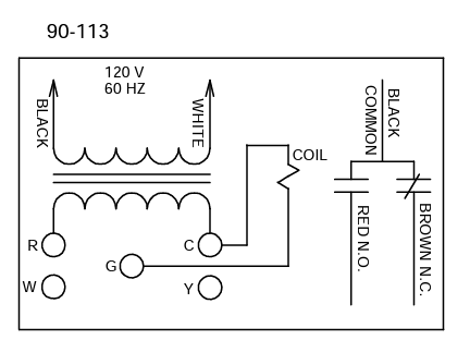
The fan center relay is basically two parts in one. You have a 115v to 24vac transformer attached, and you have a SPDT (single pole , double throw) relay. The low voltage terminal strip on the transformer gives you: R- 24vac out-put, W- basically a junction point for two or more wires, Y- another junction point for 2 or more wires, G- 24vac input to activate the relay attached, and the C terminal which is 24vac common (or ground).
The SPDT relay provides for you: 1 Common wire (black), this feeds the N.O. and N.C. contacts power. This power can be 115 or 24v, whatever you want to feed it, but generally, most give it 115vac. The Brown wire on the relay is N.C. or normally closed. This means that any power applied to the black common wire, will be sent out on the Brown wire, unless the relay is activated. Then the Brown wire becomes dead and power goes to Red N.O.. The Red wire is N.O. and there is no power on this wire unless the relay is activated.
Activating the relay is very simple. The common (or ground) side of the relay coil is already tied to the common of the transformer for us. The G terminal is the powered side of the coil, so if we take a 24v signal from R and touch it to G, the relay will activate.
Now picture a thermostat wired to this, we connect a red wire to R on the fan center, run it up the wall and connect it on R at the thermostat. If power is on we should now have 24v at R. We then connect a green wire to G on the thermostat, run it back down the wall and place it to G on the fan center. When the thermostat calls for fan, it will send 24v down the G wire, hitting the power side of the relay coil, activating it, and transferring whatever power might be on the black common wire of the relay to the Red N.O. wire.
Check out and download the attached wire diagrams file for standard wiring.