245
245
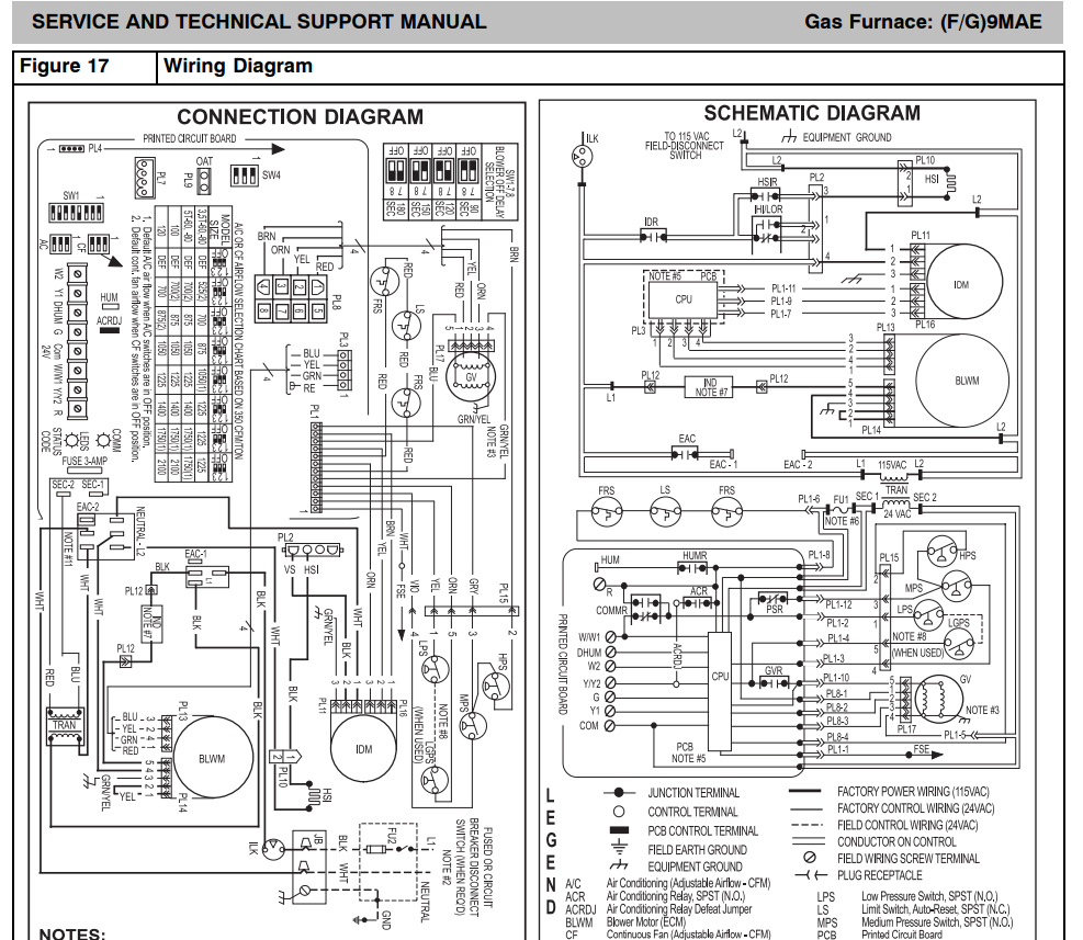
ICP G9MAE Installation/Service manuals. Vent Charts, Trouble shooting and wiring diagrams so you can service the equipment properly. ICP "Normal" operation is indicated by the "Heart-Beat" (bright-dim flash) of the green LED light on the control board. A fault condition will be indicated by the LED of the control board giving a 2 digit flash sequence, the first number represented by rapid flashes and the second with long flashes. EX: Fault 3+5 will be 3 fast flashes followed by 5 slow flashes.
NOTE: Any time power is interrupted and turned back on with a W1 (heating) call present, the system will go into a 1+2 flash and the main blower will run for 90 seconds before starting the heating sequence. If no call for heat (W1) is present during power up, the system will go directly to stand-by.
4+2 inducer fault
Check the inducer PWM line. To do this disconnect 3-pin connector PL16 from the inducer motor or the inducer motor adapter harness (when used), and connect a DC voltmeter across terminals PL16-1 BROWN (+) and PL16-2 YELLOW (-).
Note: The terminals can be permanently damaged if the voltmeter probe is jammed into the terminal end of the connector.
Use caution when checking.
Run
COMPONENT TEST by turning setup switch SW1-6 ON. Does voltage across PL16-1 and PL16-2 change between states as shown below? - State 1 – OFF (2.0 – 5.0 vdc) - State 2 – MED (9.0 – 13.0 vdc)