176
176
Proper Air Purging for Heatlink Manifold Systems
When installing a Heatlink manifold system, proper air purging is critical for optimal performance. Follow these steps to ensure an effective purge and avoid unnecessary work.
Air Purging Process:
Start by closing the supply and return water to all manifolds EXCEPT FOR THE ONE YOU ARE PURGING.
Monitor your system pressure, as air leaves the system, the pressure will drop.
-
Leave actuators off (removed from the manifold) until purging is complete. Installing them early means you’ll need to power them all on, creating extra wiring and work.
-
Use the provided manifold caps to keep loops open.
-
Purge air from each loop individually, then purge the manifold, followed by the entire system.
-
Open water to the next manifold that needs to be purged, close off the manifold that has been purged.
-
Repeat the steps until all manifolds have been purged of air.
-
Once purging is complete, open all manifold Supply and Return valves, install the actuators and finalize the setup.
-
Turn on all pumps, verify proper system pressure.
-
Heated water will release additional air trapped in the water. This is typically minimal and removed by the automatic air separator.
Following this process ensures proper system operation and reduces installation headaches.
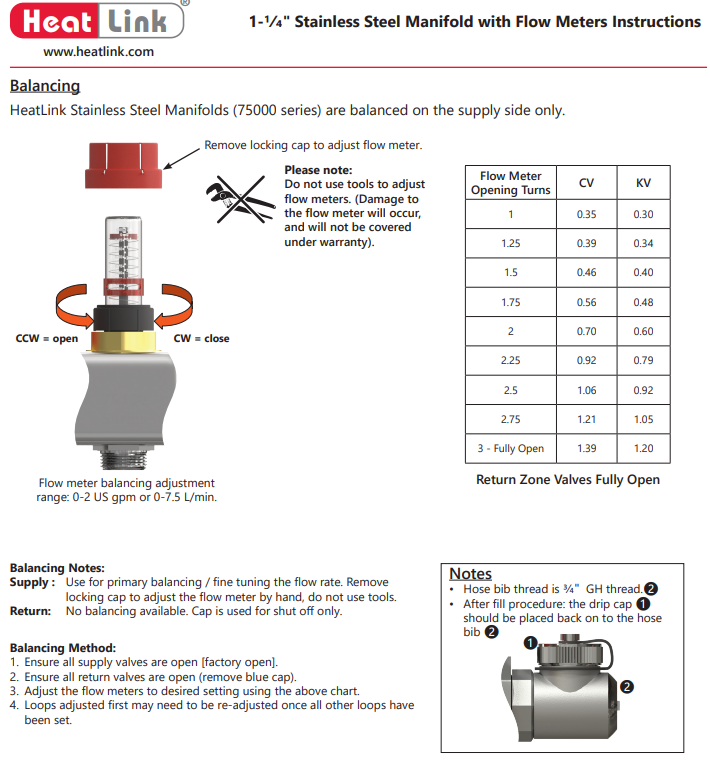
Balancing Notes: Supply:
Use for primary balancing / fine tuning the flow rate.
Remove locking cap to adjust the flow meter by hand, do not use tools. Return: No balancing available. Cap is used for shut off only.
Balancing Method:
1. Ensure all supply valves are open [factory open].
2. Ensure all return valves are open (remove blue cap).
3. Adjust the flow meters to desired setting using the above chart.
4. Loops adjusted first may need to be re-adjusted once all other loops have been set