123
123
D5CUHAH Installation Summary
Main Installation Points
Refrigerant Line Requirements
-
Minimum line length: 10 ft (3 m)
-
Standard line length: 24.6 ft (7.5 m)
-
Maximum total line length: Up to 246 ft (75 m), depending on the model
-
Maximum height separation: Up to 98.4 ft (30 m)
-
Liquid line size: 3/8 in (9.52 mm)
-
Suction line size: 3/4 in (19 mm)
-
Use flare-to-braze adapters where applicable.
-
Insulate both liquid and suction lines completely to prevent condensation.
-
Follow all torque specs and flare dimensions for secure, leak-free connections.
Refrigerant Type and Charging
-
Refrigerant type: R-454B
-
Factory charge varies by model.
-
For piping lengths over 24.6 ft, add 0.7 oz of refrigerant per foot (65 g/m).
Drainage
-
Install the provided drain joint at the base of the outdoor unit before mounting.
-
In cold climates, ensure drain hose runs vertically for proper drainage and to avoid freezing.
Outdoor Unit Mounting
-
Mount the unit on a solid base or wall bracket with appropriate clearances.
-
The base or wall must support at least four times the weight of the unit.
Electrical Installation
-
Use properly sized wire according to the unit’s nameplate MCA (Minimum Circuit Ampacity).
-
Use fork or ring terminals and ensure all connections are tight and secure.
-
Ground the system per NEC and local codes.
-
Keep control wiring separate from power lines.
-
Install an outdoor-rated surge suppressor at the disconnect.
Line Set Specifications by Model
| Model | BTU (Tons) | Liquid Line | Suction Line | Standard Length | Max Length | Max Rise | Refrigerant Charge | Additional Charge |
|---|---|---|---|---|---|---|---|---|
| D5CUHAH18AAK | 18K (1.5T) | 3/8 in | 3/4 in | 24.6 ft | 98.42 ft | 65.6 ft | 4.63 lbs (2.1 kg) | 0.7 oz/ft (65 g/m) |
| D5CUHAH24AAK | 24K (2.0T) | 3/8 in | 3/4 in | 24.6 ft | 164.04 ft | 82 ft | 4.63 lbs (2.1 kg) | 0.7 oz/ft (65 g/m) |
| D5CUHAH30AAK | 30K (2.5T) | 3/8 in | 3/4 in | 24.6 ft | 164.04 ft | 82 ft | 6.61 lbs (3.0 kg) | 0.7 oz/ft (65 g/m) |
| D5CUHAH36AAK | 36K (3.0T) | 3/8 in | 3/4 in | 24.6 ft | 246.06 ft | 98.4 ft | 7.94 lbs (3.6 kg) | 0.7 oz/ft (65 g/m) |
| D5CUHAH48AAK | 48K (4.0T) | 3/8 in | 3/4 in | 24.6 ft | 246.06 ft | 98.4 ft | 8.38 lbs (3.8 kg) | 0.7 oz/ft (65 g/m) |
| D5CUHAH60AAK | 60K (5.0T) | 3/8 in | 3/4 in | 24.6 ft | 246.06 ft | 98.4 ft | 11.46 lbs (5.2 kg) | 0.7 oz/ft (65 g/m) |
Control Scenarios
Scenario 1: 24V Thermostat with RS485 Communication (Preferred)
-
Uses a standard 24V thermostat.
-
RS485 communication links the indoor and outdoor units.
-
Do not use any 24V terminals at the outdoor unit.
-
The B and W terminals must not be used together.
-
W is only used if a conventional thermostat calls for heat at the air handler.
-
DS terminal is reserved.
Scenario 2: KSACN1401AAA Wired Controller (Factory Default)
-
Uses the factory-supplied 1401 communicating controller.
-
Full communication between indoor and outdoor units using RS485.
-
No 24V thermostat wiring required.
-
Allows access to all available system features.
-
Follow the controller’s user manual for operation and configuration.
Scenario 3: 24V Thermostat with 24V Communication (Limited Feature Mode)
-
Allows use of a standard 24V thermostat to directly control both the indoor and outdoor units.
-
Some advanced communication features will not be available.
-
Wiring includes R, C, Y1, Y2, W, B, D, and L terminals.
-
DIP Switch 2 on the outdoor unit must be set to ON.
-
Do NOT connect wires to S1 or S2 terminals.
-
Use shielded wire and ground the shield at the outdoor unit only.
-
Not recommended for dual-fuel applications using W or D terminals.
Accessories Included
| Item | Quantity | Notes |
|---|---|---|
| Drain fitting | 1 | For directing condensate from outdoor unit |
| Gasket | 1 | Not required for 48K and 60K units |
| Flare-to-braze adapter | 2 | For liquid and suction line connections |
| 5/8" to 3/4" flare adapter | 1 | For 18K Regular Heat series |
| 6-foot drain tubing | 1 | Connects to drain fitting for condensate drain |
Key Installation Considerations:
✅ Key Installation Requirements for Heat Pump System Setup
Make sure to follow these essential guidelines to ensure proper operation and avoid callback issues:
-
AHRI-Matched System
-
The outdoor and indoor units must be an AHRI-approved match to ensure efficiency, proper performance, and warranty validation.
-
-
Thermostat Wiring
-
Run a minimum 5-conductor thermostat wire to the outdoor unit to support all necessary communication and control functions.
-
-
Thermostat Compatibility
-
Use a 24V heat pump-compatible thermostat (e.g., Honeywell, Ecobee, White Rodgers). Avoid using incompatible models that lack heat pump support.
-
-
Two Power Sources
-
Ensure separate electrical power is provided to both the indoor and outdoor units. This system requires two points of power.
-
-
TXV Notice
-
Do NOT remove the TXV from the indoor unit. Factory-installed TXVs are designed to function with the matched system.
-
-
Airflow Requirements
-
Verify airflow carefully—a minimum of 350 CFM per ton is required. Poor airflow can lead to performance issues and system failure.
-
-
Outdoor Unit Configuration
-
Outdoor unit DIP switch #2 must be ON to enable Crossover Mode (used for specific control strategies or thermostat settings).
-
-
System Compatibility Warning
-
This system is NOT compatible with Communicating ION controls. If ION functionality is needed, consider using the ION Gray thermostat, as it is 24 volt.
-
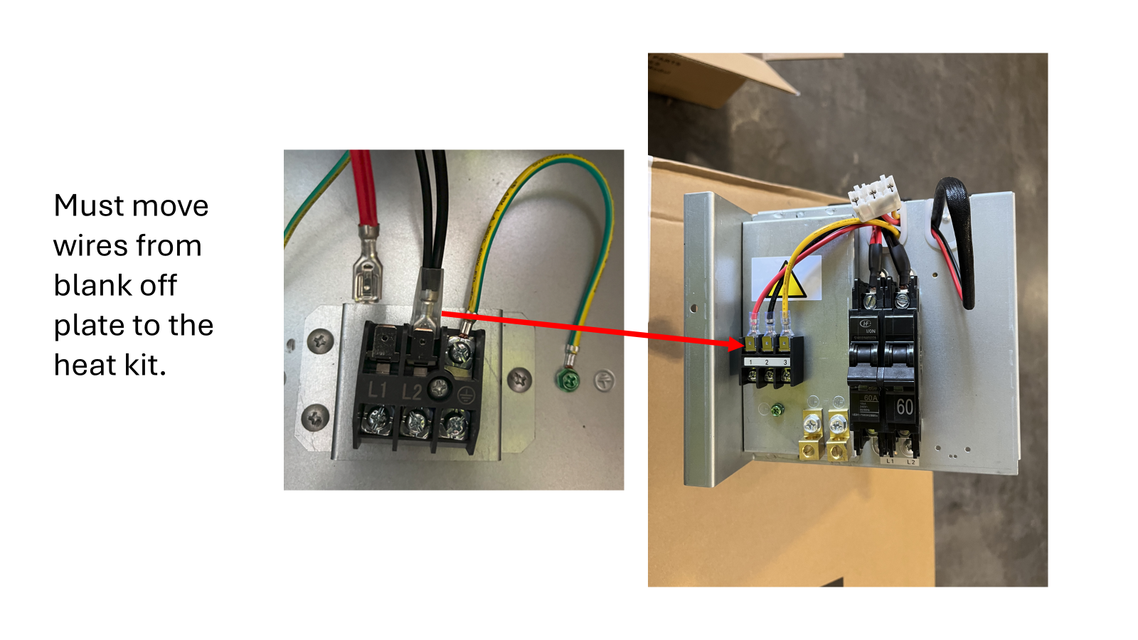
Electric heat kit:
Technical Bulletin
Subject: Wiring Procedure for Electric Heat Kit Installation
Models: D5FUAAH48XAK Air Handler (220V) with EHKMC15KN Electric Heat Kit
System Type: Scenario 2 – Communicating System
Summary
When installing the EHKMC15KN electric heat kit, the blower motor wiring is tied into the CN11 terminal block, which the kit instructions say to remove. This creates confusion on how to reconnect blower power. Carrier confirmed the original CN11 harness should not be discarded; use the harness included with the heat kit and leave the original CN11 plug loose in the cabinet.
Step-by-Step Instructions
- Power Off: Disconnect all power to the air handler before starting work.
- Remove Block-Off Plate: Follow kit instructions to remove the heater block-off plate and unplug CN11 from the terminal block.
- Do NOT Cut Blower Wires: Leave blower motor wiring intact; do not cut or discard the original harness.
- Install Electric Heat Kit: Mount the new heater assembly per kit instructions.
- Reconnect Harness:
- Use the CN11 harness provided with the electric heat kit to connect the heater kit to the control board.
- Leave the original CN11 plug and harness loose inside the cabinet (do not discard).
- Verify Connections: Ensure all connections are secure and wiring is clear of moving parts.
- Restore Power & Test: Reconnect power, run system through heating and blower operation checks.
Notes
- The original CN11 harness remains in the cabinet for future service reference.
- Do not discard any factory wiring harnesses.
- Confirm proper airflow and heat staging after installation.